The equivalent circuit of the induction motor can be used to examine the losses and the efficiency of the machine.
Efficiency is defined for an induction motor the same way as it is for any device:
\[\begin{matrix} \eta =\frac{Power\text{ }Out}{Power\text{ }In}=\frac{{{P}_{out}}}{{{P}_{in}}} & {} & \left( 1 \right) \\\end{matrix}\]
Defining the losses in the machines as Ploss , equation 1 can be written in other forms:
\[\begin{matrix} \eta =\frac{Pout}{Pout+{{P}_{loss}}}=\frac{{{P}_{in}}-{{P}_{loss}}}{{{P}_{in}}}=1-\frac{{{P}_{loss}}}{{{P}_{in}}} & {} & \left( 2 \right) \\\end{matrix}\]
Losses in the motor directly affect the cost of operation it and, indirectly, the motor rating. The efficiency is frequently determined by measuring the losses. Measurement standards are precisely defined by ANSI, IEEE, NEMA, and the Canadian Standards Association.
Types of Losses in the Induction Motor
Resistive or I2R losses are frequently referred to as copper losses and are found in the stator and rotor windings of the induction machine. Typically, in the induction motor, the stator copper loss is about 33% and the rotor copper loss is about 15% of the total loss of the machine.
Mechanical losses include friction and windage. Frequently, the mechanical losses are lumped with core loss for the induction motor and determined at the same time.
Rotational losses are typically about 14% of the total loss of the induction motor. Open-circuit or no-load core losses include the hysteresis and eddy current losses measured at no load. The sum of the mechanical and core losses is the no-load rotational loss. Core losses typically account for about 16% of the losses in the induction motor.
The stray loss includes anything not accounted for by the methods used to determine the preceding categories. Induction motor stray losses make up the remaining 22% of total losses.
Induction Motor Power Flow
The purpose of a motor, of course, is to convert electrical energy into mechanical energy. The equivalent circuit can be used to visualize and calculate the flow of power through the motor.
As shown in Figure 1, electrical power is put into the motor and is converted to heat or mechanical work. Some of the input power is lost in the core of the motor and some is dissipated in the stator winding resistance. The input power minus the core loss and stator copper loss is transferred across the air-gap, via the magnetic fields, to the rotor.
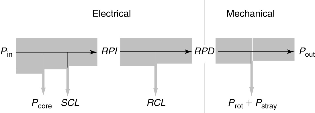
FIGURE 1 Power flow diagram for an induction motor.
The rotor winding or squirrel cage also has resistance and dissipates some power. In fact, it can be shown that the rotor copper loss is directly proportional to the slip of the motor. The remaining power is the rotor power developed (RPD), which is converted to mechanical work. Subtracting the rotational and stray losses yields the shaft power that is delivered to the load.
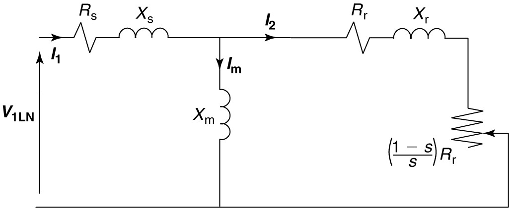
FIGURE 2 Per-phase induction motor equivalent circuit.
Looking at figure 1 and the equivalent circuit of figure 2, the stator copper loss can be calculated as:
$\begin{matrix} SCL=3I_{1}^{2}{{R}_{s}} & {} & \left( 3 \right) \\\end{matrix}$
In equation 3, SCL is the stator copper loss, I1 is the line current into the motor, Rs is the stator winding resistance per phase, and factor 3 accounts for all three phases of the motor.
If the copper losses have been measured, then the roto power input (RPI) can be determined by subtracting the SCL and Pcore from the input power:
$\begin{matrix} RPI={{P}_{in}}-SCL-{{P}_{core}} & {} & \left( 4 \right) \\\end{matrix}$
The power input to the rotor is electrical, but some is lost in the resistance of the rotor winding. The rotor copper loss is denoted by RCL. The remainder is converted to mechanical power to drive the load and make up the mechanical losses of the motor. Thus, the rotor power developed (RPD) is given by
$\begin{matrix} RPD=RPI-RCL & {} & \left( 5 \right) \\\end{matrix}$
Looking at the equivalent circuit, we could calculate the rotor current and then find the RCL. However, we know from equation 4 how much energy is transferred across the air-gap, and it can only be dissipated by the two resistances in the rotor portion of the equivalent circuit. Thus, we can find
$\begin{matrix} RCL=s\times RPI & {} & \left( 6 \right) \\\end{matrix}$
And
$\begin{matrix} RPD=(1-s)\times RPI & {} & \left( 7 \right) \\\end{matrix}$
In other words, the rotor copper loss is the slip times the rotor power input (RPI). The rotor power developed (RPD) is mechanical work, and from it, we must subtract the stray and rotational losses to obtain the actual work done at the shaft of the rotor:
$\begin{matrix} {{P}_{out}}=RPD-{{P}_{rot}}-{{P}_{stray}} & {} & \left( 8 \right) \\\end{matrix}$
Equations 3 through 8 can be used to calculate the efficiency of an induction motor, as shown in the following example.
Induction Motor Efficiency Example
The motor of 5 HP operates at rated load with a line current of 6.8 A at a slip of 1.6 %. The core, rotational, and stray losses were measured and found as follows:
$\begin{matrix} {{P}_{core}}=80W & {{P}_{rot}}=90W & {{P}_{stray}}=110W \\\end{matrix}$
Find the stator and rotor copper losses and the efficiency of the machine.
Solution
We can work this problem from both ends of the equivalent circuit to arrive at the solution. Applying equation 3 yields the stator copper loss:
$SCL=3\times {{6.8}^{2}}\times 1.21=167.8W$
We know the output power is 5 HP, so we can convert to watts:
$Pout=5\times 746=3730W$
The developed power will be the output plus the rotational and stray losses:
$RPD=3730+90+110=3930W$
The RPD is equal to (1-s) times the rotor power input (RPI), so
\[RPI=\frac{RPD}{1-s}=\frac{3930}{1-0.016}=3994W\]
The rotor copper loss (RCL) is the difference between RPI and RPD:
$RCL=3994-3930=64W$
The input power is equal to the RPI plus the stator core loss (SCL) and the core losses:
${{P}_{in}}=3994+167.8+80=4242W$
And the efficiency is
\[\eta =\frac{{{P}_{out}}}{{{P}_{in}}}=\frac{3730}{4242}\times 100=87.9%\]