When an ac voltage is applied to a capacitor, the plates charge and discharge repeatedly. During the first half-cycle, the plates charge up (one plate negative and one plate positive) and discharge back to zero.
During the next half-cycle, the plates charge to the opposite polarities of the first half cycle and then discharge back to zero. An ac meter in the circuit shows a current flowing at all times.
To demonstrate this fact, connect a light and capacitor in series with a six-volt dc source, Figure 1. Does the light glow?
Now connect the same circuit with a six-volt ac source. Notice that the light burns dimly. This experiment demonstrates that alternating current is flowing as a result of the alternate charging and discharging of the capacitor.
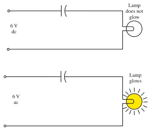
Figure 1. A light will not glow when connected to a dc source. The capacitor blocks direct current. When connected to an ac source, the light glows.
To review, refer to Figure 2. As the ac voltage starts to rise, current is at maximum because the capacitor, C, is in a discharged state. As C becomes charged to the peak ac voltage, the charging current drops to zero (point A).
As the voltage begins to drop, the discharging current begins to rise in a negative direction. It reaches a maximum at the point of zero voltage (point B). This phase difference keeps going throughout each cycle. In a purely capacitive circuit, the current leads the voltage by an angle of 90 degrees.
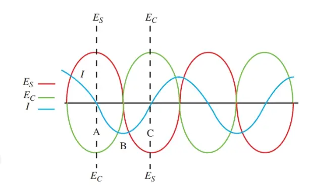
Figure 2. When a circuit is connected to ac, applied voltage, current, and the voltage across C appear as shown.
Capacitor Impedance or Capacitive Reactance
The size of the current in the circuit depends upon the size of the capacitor. Larger capacitors (more capacitance) require a larger current to charge them. The frequency of the ac voltage also affects the current.
The current depends upon the rate of charge and discharge of the capacitor. As the frequency of the ac is increased, current increases. These links are stated in the formula:
\[{{X}_{C}}=\frac{1}{2\pi fC}\]
Where XC equals the capacitive reactance (or capacitor impedance) in ohms, f equals the frequency in hertz, and C equals the capacitance in farads.
Like inductors, capacitors produce resistance to the flow of an alternating current. This resistance resulting from capacitance is called capacitive reactance (or capacitor Impedance).
Capacitive reactance is measured in ohms, like dc resistance. As you can see from the formula:
- As the frequency increases, XC
- As capacitance increases, XC
Capacitor Impedance Calculation Example
What is the reactance (impedance) of a 10 μF capacitor working in a circuit at a frequency of 120 hertz?
\[{{X}_{C}}=\frac{1}{2\pi fC}=\frac{1}{2\pi *\left( 120Hz \right)*\left( 10*{{10}^{-6}}F \right)}=132.7\Omega \]
The reactance of a 0.1 μF capacitor as the frequency is varied can be seen in Figure 3. As frequency is changed to 50, 100, 1000, and 5000 Hz, each reactance is computed using the formula for capacitive reactance (capacitor impedance). Notice how the reactance on the graph approaches zero as the frequency heads toward infinity.

Figure 3. As frequency increases, capacitive reactance (capacitor impedance) decreases.
In Figure 4, the frequency is held constant at 1000 Hz. The reactance is plotted for capacitors of 0.01 μF, 0.05 μF, 0.1 μF, and 0.5 μF. These are common capacitor sizes used in electronic work. They are used in filtering, coupling, and bypassing networks.
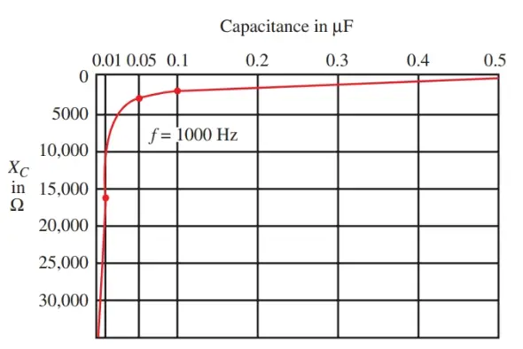
Figure 4. As capacitance increases, reactance decreases.
Power in a Capacitive Circuit
When a capacitor is discharged, the energy stored in the dielectric is returned to the circuit. This action is similar to the action of an inductor, which returns the energy stored in a magnetic field to the circuit.
In both cases, electrical energy is used temporarily by the reactive circuit. This power in a capacitive circuit is also called wattles power.
In Figure 5, the voltage and current waveforms are drawn for a circuit containing pure capacitance. The power waveform results from plotting the products of the instantaneous voltage and current at selected points.
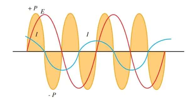
Figure 5. These waveforms show current, voltage, and power in a purely capacitive circuit.
The power waveform shows that equal amounts of positive power and negative power are used by the circuit. This condition results in zero power being used. The true power, or actual power used, then, is zero.
The apparent power is equal to the product of the effective voltage and the effective current. Look at Figure 6. An applied ac voltage to the capacitive circuit causes a 10-ampere current. The apparent power will equal:
\[\begin{align} & Apparent\text{ }Power={{E}_{eff}}\times {{I}_{eff}} \\ & Apparent\text{ }Power=100V\times 10A=1000VA \\\end{align}\]
Power Factor
The ratio of true power to apparent power in an AC circuit is called the power factor (PF).
It is found using trigonometry. It is the cosine of the phase angle between the current and the voltage.
\[\text{Power Factor=cos}\theta \text{=}\frac{\text{True Power}}{\text{Apparent Power}}\]
Power Factor Example
Assuming our previous circuit is purely capacitive, determine the power factor and phase displacement.
\[\text{Power Factor=cos}\theta \text{=}\frac{0}{1000}=0\]
The angle whose cosine is 0 is 90 degrees. This tells us that current and voltage in the purely capacitive circuit are 90 degrees out of phase.
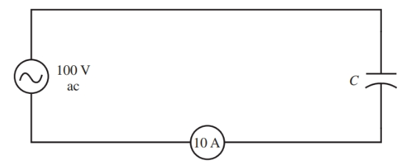
Figure 6. Schematic for the theoretical capacitive circuit.
Resistance and Capacitance in an AC Circuit
When resistance is present in a circuit, power is used. If a circuit contains only resistance, then the voltage and current are in phase. There is no phase angle θ, and the power factor is one (cos 0° = 1). The apparent power equals the true power.
These circuit traits change when the capacitance is added in series with the resistor. Capacitive reactance (Capacitor Impedance) is also a force which resists the flow of an alternating current.
Because the capacitive reactance causes a 90-degree phase displacement, the total resistance to an ac current must be the vector sum of XC and R. These vectors are drawn in Figure 7.
Assuming the AC circuit has a resistance of 300 ohms and a capacitive reactance (capacitor impedance) of 400 ohms, the resulting opposition to current is 500 ohms. This opposition is called the impedance (Z), of the circuit.
$Z=\sqrt{{{R}^{2}}+X_{C}^{2}}=\sqrt{{{300}^{2}}+{{400}^{2}}}=500\Omega $
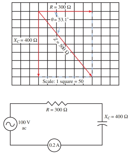
Figure 7.
Top. The vector relationship between R and XC and the resulting vector, Z, for impedance. Bottom. The AC circuit for the problem in the text.
The angle between vector Z and vector R represents the phase displacement between the current and the voltage as a result of the reactive component. This is angle θ. Since cosine θ is equal to the power factor, we can calculate using:
\[\cos \theta =PF=\frac{R}{Z}=\frac{300\Omega }{500\Omega }=0.6\]
An angle with a cosine of 0.6 is 53.1 degrees (approximately). Thus, the current leads the voltage by an angle of 53.1 degrees.
The true power in this circuit equals:
\[\text{True Power=Apparent Power}\times \cos \theta \]
The power factor is also the relationship between the true power and the apparent power. Since cos θ equals the power factor, it follows that:
$\begin{align} & True\text{ }Power=Apparent\text{ }Power\times Power\text{ }Factor \\ & or \\ & PF=\frac{True\text{ }Power}{Apparent\text{ }Power} \\\end{align}$
Using Ohm’s law for ac circuits, the current flowing in Figure 7 (100 volts ac applied) is equal to:
\[I=\frac{E}{Z}=\frac{100V}{500}=0.2A\]
The apparent power is then:
$ApparentPower=I*E=0.2A*100V=20VA$
True power equals:
$True\text{ }Power=I*E*\cos \theta =0.2A*100V*\cos {{53.1}^{o}}=12W$
Parallel RC Circuit
- In an AC circuit containing a resistance and a capacitance in parallel, the voltage of each circuit element will be the same as the source voltage.
- Further, there will be no phase difference among the voltages. This is because they are all in parallel.
- There will, however, be a phase difference among the total and branch currents. The current is in phase with voltage in the resistive branch.
- The current leads the voltage across the capacitor by 90 degrees.
- The total current leads the source voltage by some angle between 0 and 90 degrees.
- If the reactance of the capacitor is larger than the resistance of the resistor, θ will be closer to 0 degrees. If the resistance is much larger than the reactance θ will be closer to 90 degrees.
- In the parallel RC circuit, we do not find impedance through a vector sum of circuit resistances. Instead, we apply Ohm’s law after finding the sum of the branch currents.
\[Z=\frac{{{E}_{S}}}{{{I}_{T}}}\]
- As stated, the voltage in the parallel RC circuit is in phase with IR, and it lags IC by 90 degrees. Thus, we can say that IR lags IC by 90 degrees.
- The parallel RC circuit, then, has two current components—IR and IC. Both of these can be represented by phasors. Since they are out of phase, we cannot simply add the two components together to figure the total circuit current. We must find their phasor sum.
${{I}_{T}}=\sqrt{I_{R}^{2}+I_{C}^{2}}$
- Note that the phasor for IC is above the horizontal reference. This is because IC leads voltage—the horizontal reference for the parallel RC circuit.
- For the parallel RC circuit, the phase angle is found on the current phasor diagram. The horizontal reference of this circuit is voltage since it is common to all circuit elements. On the current phasor diagram, the horizontal component is IR since it is in phase with the voltage.
- The phase angle, then, is the angle between IR and the total current. This is the phase displacement resulting from the reactive element. In the parallel RC circuit, the phase angle is:
\[\theta =\arctan \left( \frac{{{I}_{C}}}{{{I}_{R}}} \right)\]
Phase Angle & Impedance Calculation Example
Using the AC circuit with assigned values in Figure 8, determine the phase angle between the applied voltage and current. Draw the current phasor diagram and find the circuit impedance.
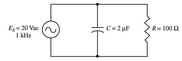
Figure 8. A parallel RC circuit.
Step 1. Compute the value of capacitive reactance, XC.
\[{{X}_{C}}=\frac{1}{2\pi fC}=\frac{1}{2\pi *\left( 1*{{10}^{3}} \right)*\left( 2*{{10}^{-6}} \right)}=80\Omega \]
Step 2. Compute the branch currents. Using Ohm’s law:
$\begin{align} & {{I}_{R}}=\frac{{{E}_{S}}}{R}=\frac{20V}{100\Omega }=0.2A \\& {{I}_{C}}=\frac{{{E}_{S}}}{{{X}_{C}}}=\frac{20V}{100\Omega }=0.25A \\\end{align}$
Step 3. Determine the phase angle to see by how much the circuit current leads the voltage.
\[\theta =\arctan \left( \frac{{{I}_{C}}}{{{I}_{R}}} \right)=\arctan \left( \frac{0.25}{0.2} \right)={{51.3}^{o}}\]
Step 4. Draw the current phasor diagram. Use any convenient scale. Remember that IR is drawn as the horizontal component. IC is drawn upward at 90 degrees from IR since it leads voltage—the horizontal reference. See Figure 9.
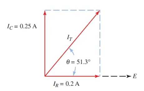
Figure 9. Current phasor diagram.
Step 5. Find the total circuit current.
\[{{I}_{T}}=\sqrt{I_{R}^{2}+I_{C}^{2}}=\sqrt{{{0.2}^{2}}+{{0.25}^{2}}}=0.32A\]
Step 6. Find the impedance of the circuit. Using Ohm’s law:
\[Z=\frac{{{E}_{S}}}{{{I}_{T}}}=\frac{20V}{0.32A}=62.5\Omega \]
All circuits have some combination of the three electrical properties: R, L, and C. These properties come in many arrangements, including R, RL, and RC networks.