Capacitors in DC Circuits
When a capacitor is placed in a DC circuit that is closed (current is flowing) it begins to charge. Charging is when the voltage across the plates builds up quickly to equal the voltage source. Once a capacitor reaches its fully charged state, the current flow stops.
Once a charged capacitor is disconnected from a circuit it will remain charged. To discharge a capacitor, it will need to be placed in a closed circuit without a voltage source. Most of the time a wire is used to connect the two ends of a capacitor for rapid discharging. However, that is dangerous and caution should be used when discharging a capacitor.
RC or resistor-capacitor circuits are a basic type of circuit. The charging or discharging of a capacitor requires time, and different capacitors have different charging times. The RC time constant is the fixed time interval which is equal to the resistance times the capacitance in a series RC circuit. The time constant determines the charging/discharging rate for a capacitor. See the following equation:
\[\mathbf{\tau }\text{ }=\text{ }\mathbf{R}\text{ }\mathbf{x}\text{ }\mathbf{C}\]
R is resistance,
C is capacitance,
τ is RC time constant
Capacitors in DC Circuits Example 1
Find the time constant for the following RC circuit: a 500 Ω resistor and a 20 µF capacitor.
Plug the values into the equation.
\[\tau =500\text{ }\Omega \text{ }\times \text{ }20\text{ }\mu F\]
Solve. The time constant unit is seconds.
\[\mathbf{\tau }\text{ }=0.01\text{ }s\]
Capacitors in DC Circuits Example 2
If a 3.5 kΩ resistor is connected to a .5 µF capacitor, what will the time constant be?
Multiply the resistance and the capacitance.
\[\mathbf{\tau }\text{ }=3500\text{ }\Omega \text{ }\times .5\text{ }\mu F\]
Solve.
\[\text{ }\tau \text{ = 0}\text{.00175 s or 1}\text{.75 ms}\]
Charging and discharging of a capacitor on a graph is not linear. It has an exponential curve to the charging and discharging. See Figure 1 for the charging curve.
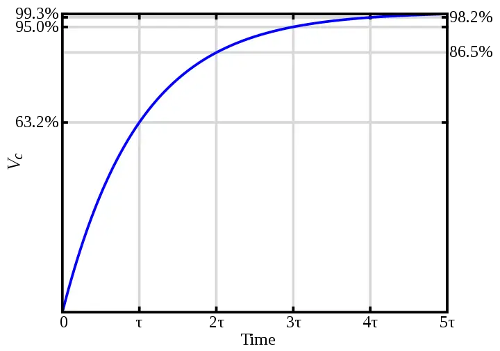
Figure 1 Series RC capacitor voltage
Note that the graph is broken down into five-time constants. In five time constants, the capacitor reaches 99% (rounded to 100%) charging or discharging. Transient time is the five-time constants or the time to fully charge/discharge a capacitor.
To calculate the charging/discharging voltage and current of a capacitor use the following equations:
\[\begin{matrix} \mathbf{v}\text{ }=\text{ }{{\mathbf{V}}_{\mathbf{F}}}+\text{ }\left( {{\mathbf{V}}_{\mathbf{i}}}\text{ – }{{\mathbf{V}}_{\mathbf{F}}} \right)\text{ }.\text{ }{{\mathbf{e}}^{-{}^{t}/{}_{\tau }}} & {} & \left( 1 \right) \\\end{matrix}\]
Where,
v is instantaneous voltage,
VF is final voltage
Vi is initial voltage
e is exponential number
t is time
τ is time constant
\[\begin{matrix} i={{I}_{\mathbf{F}}}+\text{ }\left( {{I}_{\mathbf{i}}}-{{I}_{\mathbf{F}}} \right)\text{ }.\text{ }{{\mathbf{e}}^{-{}^{t}/{}_{\tau }}} & {} & \left( 2 \right) \\\end{matrix}\]
Where,
i is instantaneous current,
IF is final current
Ii is initial current
e is the exponential number
t is time
τ is time constant
\[\begin{matrix} \mathbf{v}\text{ }=\text{ }{{\mathbf{V}}_{\mathbf{F}}}\left( \mathbf{1}\text{ – }{{\mathbf{e}}^{-{}^{t}/{}_{RC}}} \right) & {} & \left( 3 \right) \\\end{matrix}\]
Where,
v is instantaneous voltage,
VF is the final voltage
e is the exponential number
t is time
τ is time constant
Capacitors in DC Circuits Example 3
After 2 seconds what is the charged voltage in the RC circuit: a 200 Ω resistor, a 4 µF capacitor, and a 6 V voltage source (see Figure 2).
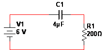
Figure 2 Circuit schematic with the resistor connected to a capacitor and DC voltage source
Calculate the exponent (Equation 3)
\[\frac{-2}{\left( 200\text{ }\Omega \times \text{ }4\text{ }\mu F \right)}\]
Using the exponent, calculate what’s inside the ( )
1 – e-2500
Multiply that by the voltage source (the final voltage.)
6 V x 1
Solve.
v = 6 V
Capacitors in DC Circuits Example 4
If only .5 seconds pass from the time that the switch is thrown and 9 V is applied to 3.5 k Ω resistor and a 15 µF capacitor (see Figure 3). What is the charge on the capacitor?
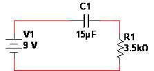
Figure 3: Circuit schematic DC voltage connected to an RC circuit
Find the exponent (Equation 3)
\[-\frac{0.5}{\left( 3500\text{ }\Omega \times \text{ }15\text{ }\mu F \right)}~\]
Calculate what’s inside the ( )
1 – e-9.5238
Multiply by the final voltage.
9 V x .9999
Solve.
v = 8.999 V
Calculating the discharge is similar to the charging, but the equation is different. Since discharging ends at zero, the equation is simplified to:
\[\begin{matrix} \mathbf{v}\text{ }=\text{ }{{\mathbf{V}}_{\mathbf{i}}}\text{ }\times \text{ }\left( {{\mathbf{e}}^{{{-}^{t}}{{/}_{RC}}}} \right) & {} & \left( 4 \right) \\\end{matrix}\]
Where,
v is instantaneous voltage,
Vi is initial voltage
e is the exponential number
t is time
τ is time constant
Capacitors in DC Circuits Example 5
A capacitor charged to 5 V is discharged for .2 seconds. The capacitor is rated at 5 µF and the resistor is 1000 Ω. Is the capacitor completely discharged?
Calculate the exponent ( Equation 4)
\[-\frac{0.2}{\left( 1000\text{ }\Omega \times \text{ }5\text{ }\mu F \right)}\]
Plug in the values.
5 V x e-40
Find the remaining voltage.
2.124 x 10⁻¹⁷ V
Since the voltage left is practically zero, the capacitor is discharged.
Capacitors in DC Circuits Example 6
A 35 µF capacitor has a 10 V charge on it. If it is connected to a 2 k Ω resistor for .1 seconds, what is the remaining charge?
Find the exponent (Equation 4)
\[-\frac{0.1}{\left( 2000\text{ }\Omega \times \text{ }35\text{ }\mu F \right)}\]
Plug in the values.
10 V x e-1.4286
Solve.
v = 2.397 V
Figure 4 shows the effect a capacitor has on a square wave. Instead of pulsing up, the wave slowly charges up to the max value. Then it slowly discharges the voltage, rather than drop down to zero.
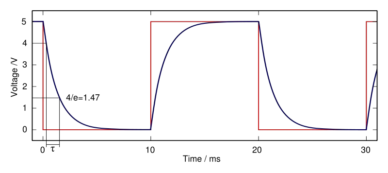
Figure 4 Capacitor Square wave charge-discharge
Capacitors in AC circuits
Capacitors in AC circuits are trickier than DC. This is due to the alternating current. In AC circuits capacitors resist the current. The capacitive reactance is the capacitor resisting the sinusoidal current and is symbolized by XC. Since it is resisting the flow of current the unit for capacitive reactance is ohm. It is dependent on both the frequency and the capacitance, see the following equation:
\[\begin{matrix} {{X}_{C}}=\frac{1}{2\text{ }\pi fC} & {} & \left( 5 \right) \\\end{matrix}\]
XC is capacitive reactance (Ω),
f is frequency (Hz)
C is capacitance (F)
Capacitors in AC Circuits Example 7
An 8 µF capacitor is connected to a 6 Vrms with a frequency of 400 Hz (see Figure 5). What is the capacitive reactance?
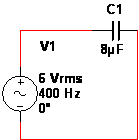
Figure 5 Circuit schematic with one capacitor connected to an AC voltage source
Calculate the bottom part of the equation 5:
\[2\pi \text{ }\times \text{ }400\text{ }Hz\text{ }\times \text{ }8\text{ }\mu F\]
Then take one divided by what you calculated.
\[\frac{1}{0.02011}\]
Solve. The 6 Vrms was unimportant for solving the capacitive reactance.
XC =49.74 Ω
Capacitors in AC Circuits Example 8
If 10 Vrms with a frequency of 3 kHz is applied to a 60 µF capacitor (see Figure 6), what will the capacitive reactance be?
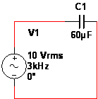
Figure 6 Circuit schematic AC voltage connected to one capacitor
Calculate the denominator (Equation 5)
\[2\pi \text{ }\times \text{ }3000\text{ }Hz\text{ }\times \text{ }60\text{ }\mu F\]
One divided by the denominator.
\[\frac{1}{1.13097}\]
Solve.
XC =0.884 Ω
Whenever the capacitors are in series and AC is applied, the capacitive reactance for each capacitor behaves as resistors do. The XC is added together for capacitors in series. See the following equation:
\[{{\mathbf{X}}_{\mathbf{C}(\mathbf{total})}}=\text{ }{{\mathbf{X}}_{\mathbf{C1}}}+\text{ }{{\mathbf{X}}_{\mathbf{C2}}}+\text{ }{{\mathbf{X}}_{\mathbf{C3}}}+\ldots .+\text{ }{{\mathbf{X}}_{\mathbf{Cn}}}\]
Capacitors in AC Circuits Example 9
A voltage source has a frequency of 700 Hz and two capacitors rated at 2 µF and .03 µF are connected in series (see Figure 7). What is the total capacitive reactance?

Figure 7 Circuit schematic AC voltage source with two series capacitors
Calculate the capacitive reactance for both capacitors.
\[{{X}_{C1}}=\frac{1}{2\text{ }\pi \times 700\text{ }Hz\text{ }\times 2\text{ }\mu F}~~=113.68\Omega \]
\[{{X}_{C2}}=\frac{1}{2\text{ }\pi \times 700\text{ }Hz\times .03\text{ }\mu F}~=7578.81\Omega \]
Add them together for the XC (total)
\[{{\mathbf{X}}_{\mathbf{C}\left( Total \right)}}=113.68\Omega +\text{ }7578.81\Omega =\text{ }7692.49\Omega \]
Since the capacitive reactance acts the same as resistors, when capacitors are in parallel you calculate the capacitive reactance using the following equation:
Equation for Calculating Total capacitive reactance for 3 or More Capacitors in parallel
\[{{\mathbf{X}}_{C\left( Total \right)}}=\frac{1}{{}^{1}/{}_{{{\mathbf{X}}_{\mathbf{C}1}}}+{}^{1}/{}_{{{\mathbf{X}}_{\mathbf{C2}}}}+{}^{1}/{}_{{{\mathbf{X}}_{\mathbf{C}3}}}+\cdots +{}^{1}/{}_{{{\mathbf{X}}_{\mathbf{C}n}}}}\]
For two capacitors, you can use the following equation:
\[{{\mathbf{X}}_{C\left( Total \right)}}=\frac{{{\mathbf{X}}_{\mathbf{C1}}}\times {{\mathbf{X}}_{\mathbf{C2}}}}{{{\mathbf{X}}_{\mathbf{C1}}}+\text{ }{{\mathbf{X}}_{\mathbf{C2}}}}\]
Capacitors in AC Circuits Example 10
What is the capacitive reactance for the following circuit (Figure 8), a 4 µF and a .06 µF capacitor connected in parallel with a source voltage that has a 900 Hz frequency?
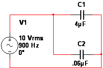
Figure 8 Circuit schematic two capacitors in parallel with AC voltage source
Find the capacitive reactance for each capacitor.
\[{{X}_{C1}}=\frac{1}{2\text{ }\pi \times 900\times 4\text{ }\mu F}=44.21\Omega \]
\[{{X}_{C2}}=\frac{1}{2\text{ }\pi \times 900\times 0.06\text{ }\mu F}=2947.31\Omega \]
Calculate the total.
\[{{X}_{C(Total)}}=\frac{44.21\Omega \text{ }\times \text{ 2947}\text{.31}\Omega }{44.21\Omega \text{ + 2947}\text{.31}\Omega }=43.56\Omega \]
Ohm’s Law still applies to figure out the circuit. With capacitors, the capacitive reactance is used instead of resistance (even though they are basically the same). So the equation looks like this:
\[\begin{align} & I=\frac{V}{{{X}_{C}}} \\ & V=I{{X}_{C}} \\\end{align}\]
Capacitors in AC Circuits Example 11
What is the current when a 6 Vrms with a frequency of 2 kHz is applied to a .2 µF capacitor (see Figure 9)?
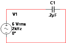
Figure 9 Circuit schematic one capacitor connected to AC voltage source
Calculate the XC.
\[\frac{1}{2\text{ }\pi \times 2000\text{ }Hz\text{ }\times \text{ }.2\text{ }\mu F}\]
Current is the voltage over the XC.
\[\frac{6\text{ }V}{397.89\Omega }\]
Solve. Keep in mind whether it is rms, pp, or p values.
I =0.015 Arms
Earlier, voltage across one capacitor was calculated using capacitance. You can achieve the same results using the capacitive reactance. See the following equation:
\[{{V}_{x}}=\left( \frac{{{X}_{Cx}}}{{{X}_{C(total)}}} \right){{V}_{s}}\]
Where XCx is the capacitive reactance of the capacitor with unknown voltage.
Capacitors in AC Circuits Example 12
What is the voltage across a 4 µF capacitor connected in series to a .75 µF, with a voltage source of 6 Vrms and a frequency of 850 Hz (see Figure 10).
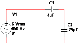
Figure 10 Circuit schematic two capacitors in series with AC voltage source
Calculate the XC for the capacitors.
\[\begin{align} & {{X}_{C1}}=\text{ }\frac{1}{2\text{ }\pi \times 850\text{ }Hz\times 4\text{ }\mu F}=46.81\Omega \\ & {{X}_{C2}}=\text{ }\frac{1}{2\text{ }\pi \times 850\text{ }Hz\times 0.75\text{ }\mu F}=249.65\Omega \\ & {{X}_{C\left( Total \right)}}=46.81\Omega +249.65\Omega =296.46\Omega \\\end{align}\]
Plug the values into the equation.
\[{{V}_{x}}=\frac{46.81\Omega }{296.46\Omega }\times 6\text{ }{{V}_{rms}}=0.947{{V}_{rms}}\]
Instantaneous power is the instantaneous current times the instantaneous voltage. It allows you to see the power at any point, as long as current and voltage are known.
Ideally, all the power would be stored and then returned to the circuit. The result is the true power, which is the power lost or dissipated in a circuit, typically as heat, being zero. But a small amount of total power is lost because the capacitors are not perfect.
Reactive power (Pr) is the rate that energy is either stored or returned from a capacitor. The unit for reactive power is VAR (volt-ampere reactive).To find the Pr the following equations are used:
\[\begin{align} & {{\operatorname{P}}_{r}}={{V}_{rms}}{{I}_{rms}} \\ & {{\operatorname{P}}_{r}}={}^{V_{rms}^{2}}/{}_{{{X}_{C}}} \\ & {{\operatorname{P}}_{r}}=I_{rms}^{2}{{X}_{C}} \\\end{align}\]
Capacitors in AC Circuits Example 13
If the source voltage is 6 Vrms and the XC is 356 Ω, what is the reactive power?
Plug the values into the correct equation.
\[{{\operatorname{P}}_{r}}=\frac{V_{rms}^{2}}{{{X}_{C}}}=\frac{{{6}^{2}}}{356}=0.101\text{ }VAR\]
- You May Also Read : Inductors in AC and DC Circuits