In spite of the great number of different kinds of inductors, only a few schematic symbols are needed to represent them.
Filter Choke
A filter choke for a power supply is shown in figure 1 (a), and its symbol is shown in figure 1(b).
Fig.1: Iron Core Choke Coil: (a) Typical Choke. (b) Schematic Symbol
You May Also Read: Inductor Questions and Answers
The two parallel lines beside the coil represent an iron core. Inductors with iron cores are suitable for use only with a power line and audio frequencies. Above the audio range (approximately 20 kHz), the losses in the core become too large to be practical.
Radio Frequency Coils
Typical radio frequency (RF) coils are shown in figure 2 (a), and the symbol is shown in figure 2 (b).
Fig.2: Radio Frequency Coil: (a) Typical RF Coil. (b) Schematic Symbol (c): Schematic Symbol for Coil with Adjustable Ferrite Core
No iron core is used at these frequencies. Many RF coils have a ferrite slug or powered iron core inside the coil, which can be screwed in or out. The symbol for such a device is represented in figure 2 (c). Because of the high permeability of this kind of core, the inductance value can be made to vary over an appreciable range.
Transformer
Another popular type of inductor is the transformer, which can be used with power and audio frequencies as well as radio frequencies. Some typical transformer and their schematic symbols are shown in figure 3. Note the primary and secondary windings for transformers.
Fig.3: Transformers: (a) RF Transformer. (b) Schematic Symbol for RF Transformer. (c) Power Transformer. (d) Schematic Symbol for Power Transformer
Toroid
A very common type of inductor is the toroid, a small doughnut-shaped coil, as shown in figure 4.
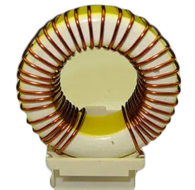
Fig.4: Toroid with Toroidal Winding
The coil may consist of a single-layer winding, a multilayer winding, or even several coils wound on the same toroid. The core is of ferrite material, which has a high permeability. Consequently, the inductance can be quite large for the number of turns. Practically, all the flux in confined to the core, and very little shielding is required to prevent interference with adjacent components.
Sometimes, it is necessary to have inductors that can vary the amount of RF energy or coupling between primary and secondary windings. Such an inductor is shown in figure 5 (a). In figure 5 (b), a variable or adjustable inductor is represented in schematic form.
Fig.5: Schematic Symbols for Variable Inductors: (a) Variable-Coupling RF Transformer. (b) Adjustable Coil.
Power Supply Inductor
Figure 6 shows the circuit of an inductor used with a dc power supply, and figure 7 shows the appearance of a typical power supply inductor.
Fig.6: An inductor can be used with a dc power supply to smooth the input ripple voltage without affecting the dc voltage level
Fig.7: Typical power supply inductor
In the application, the inductor is usually required to pass a direct current that has a fluctuating level. Because the inductor opposes any change in the current level through its windings, it tends to smooth out the fluctuations (see the waveforms in figure 6). This is exactly why the inductor is employed in this particular application. Because of the presence of the direct current through the windings, it is the incremental inductance of this component that is important. Therefore, the inductance value must be specified at a given level of direct current. Typical values for such inductors range from 50 mH to 20 H, with direct currents up to about 10 A and insulation voltage ratings up to 1000 V.
High-frequency inductor
In figure 8, a low-current high-frequency type of inductor is illustrated. The core, in this case, is a ferrite material in two mating sections known as a pot core. As well as increasing coil’s inductance, the pot core shields the coil to safeguard neighboring components against any type of flux leakage issues and to save the coil from outer magnetic fields. The coil is wrapped on a bobbin, so its turns are comfortably altered.
Fig.8: low-current high-frequency ferrite pot core inductor
You May Also Read: