Parallel Circuit Definition
Resistors are said to be connected in parallel when the same voltage appears across every component. With different resistance values, different currents flow through each resistor.
Resistance, Inductance, and Capacitance in Parallel Circuit
The characteristic of a parallel circuit is that the same voltage appears across all parallel branches. We use this common voltage as the reference phasor in phasor diagrams for any parallel AC circuits. Ohm’s law then gives the current through each branch of the circuit in Figure 1.
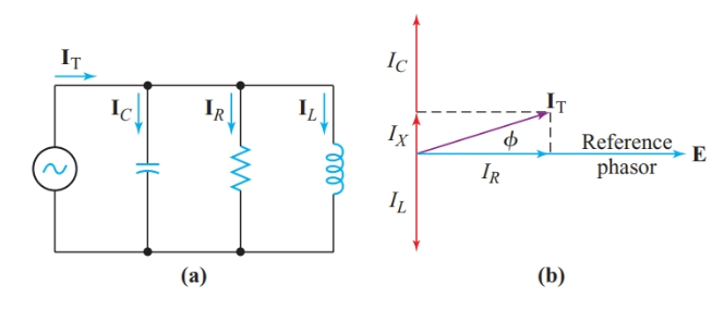
Figure 1 A parallel circuit containing resistance, inductance, and capacitance
For the resistance,
\[{{\text{I}}_{\text{R}}}=\frac{E\angle {{0}^{o}}}{R\angle {{0}^{o}}}=\frac{E}{R}\angle {{0}^{o}}\]
Therefore, IR is in phase with the applied voltage.
For the inductance,
\[{{\text{I}}_{\text{L}}}=\frac{E\angle {{0}^{o}}}{{{X}_{L}}\angle +{{90}^{o}}}=\frac{E}{{{X}_{L}}}\angle -{{90}^{o}}\]
And IL lags behind the reference voltage by 90°.
For the capacitance,
\[{{\text{I}}_{\text{C}}}=\frac{E\angle {{0}^{o}}}{{{X}_{C}}\angle -{{90}^{o}}}=\frac{E}{{{X}_{C}}}\angle +{{90}^{o}}\]
And IC leads the reference voltage by 90°.
The total current in the parallel circuit is the phasor sum of the branch currents:
\[\begin{matrix}{{I}_{T}}={{I}_{R}}-j{{I}_{L}}+j{{I}_{C}}={{I}_{R}}+j\left( {{I}_{C}}-{{I}_{L}} \right) & {} & \left( 1 \right) \\\end{matrix}\]
Converting Equation 1 to polar coordinates gives
$\begin{matrix}{{\text{I}}_{\text{T}}}=\sqrt{I_{R}^{2}+I_{X}^{2}}\angle {{\tan }^{-1}}\frac{{{I}_{X}}}{{{I}_{R}}} & {} & \left( 2 \right) \\\end{matrix}$
Where IX is the net reactive current IC – IL.
We can apply the following equation to determine the equivalent impedance of the parallel circuit:
\[\begin{matrix}{{\text{Z}}_{\text{eq}}}\text{=}\frac{\text{E}}{{{\text{I}}_{\text{T}}}} & {} & \left( 3 \right) \\\end{matrix}\]
This method of solving for the equivalent impedance of a parallel circuit is called the total-current method. If the applied voltage is not known, we can assume any convenient value in order to find the equivalent impedance.
Conductance, Susceptance, and Admittance
For parallel DC circuits, it is convenient to think in terms of conductance, the reciprocal of resistance. Conductance is a measure of how easily a DC circuit passes current. We can use a similar approach for AC circuits. Since I = E/Z, we can rewrite Equation 1 as
\[\frac{E\angle {{0}^{o}}}{\text{Z}}=\frac{E}{\text{Z}}=\frac{E}{R}-j\frac{E\angle {{0}^{o}}}{{{X}_{L}}}+j\frac{E\angle {{0}^{o}}}{{{X}_{C}}}\]
Dividing by E gives
\[\begin{matrix}\frac{1}{\text{Z}}=\frac{1}{R}-j\frac{1}{{{X}_{L}}}+j\frac{1}{{{X}_{C}}} & {} & \left( 4 \right) \\\end{matrix}\]
In this equation, we can replace 1/R with conductance, G. There are similar reciprocals for impedance and reactance.
Admittance is the overall ability of an electric circuit to pass alternating current. The symbol for admittance is Y. Admittance is the reciprocal of impedance: Y = 1/Z
Susceptance is the ability of inductance or capacitance to pass alternating current. The letter symbol for susceptance is B. Susceptance is the reciprocal of reactance: B = 1/X
The SI unit for both admittance and susceptance is the Siemens, the same as for conductance.
When we divide 1∠0° by a phasor quantity with a +90° angle, the quotient has a -90° angle. Hence, the reciprocal of +jXL is -jBL. Similarly, the reciprocal of -jXC is +jBC. Thus, substituting admittance, conductance, and susceptance into Equation 4 gives
$\begin{matrix}Y=G-j{{B}_{L}}+j{{B}_{C}}=G+j\left( {{B}_{C}}-{{B}_{L}} \right) & {} & \left( 5 \right) \\\end{matrix}$
The polar coordinates of admittance are
\[\begin{matrix}Y=\sqrt{{{G}^{2}}+B_{eq}^{2}}\angle {{\tan }^{-1}}\frac{{{B}_{eq}}}{G} & {} & \left( 6 \right) \\\end{matrix}\]
Where Beq is the net equivalent susceptance, BC – BL.
Since BL = 1/XL,
\[\begin{matrix}{{B}_{L}}=\frac{1}{2\pi fL}=\frac{1}{\omega L} & {} & \left( 7 \right) \\\end{matrix}\]
Similarly,
$\begin{matrix}{{B}_{C}}=2\pi fC=\omega C & {} & \left( 8 \right) \\\end{matrix}$
Summary
• In a parallel AC circuit, the total current is the phasor sum of all the branch currents.
• Admittance is the overall ability of an electric circuit to pass alternating current.
• Susceptance is a measure of the ability of inductance or capacitance to pass alternating current.
• Admittance is the reciprocal of impedance.
• The rectangular coordinates of impedance are resistance and reactance.
•The rectangular coordinates of admittance are conductance and susceptance