In an alternating-current circuit, power is dissipated in a resistor, but not in a pure inductor or a capacitor. Because the current in an RL circuit lags the supply voltage by an angle ϕ, the amount of useful power supplied to the circuit is proportional to Cosϕ. Similarly, in an RC circuit, the useful power is proportional to the angle by which the current leads the voltage.
The presence of the reactive components causes reactive power to be supplied to the circuit. This gives an apparent power, which is greater than the true power utilized in the circuit. The ratio of true power to apparent power is termed the power factor of the circuit.
Power Dissipated in a Resistance
When an alternating current flows in a resistance, the power dissipated can be calculated as follows:
$\begin{matrix} P=EI & {} & \left( 1 \right) \\\end{matrix}$
Where E and I are RMS values. As long as RMS quantities are used for voltage and current, the power calculations for a resistor in an AC Circuit are exactly the same as those for a DC circuit. Thus, we can write the following equations to compute the power:
$P={{I}^{2}}R$
And
\[P=\frac{{{E}^{2}}}{R}\]
Where E and I are again the RMS values.
Figure 1 shows that the instantaneous power dissipated in a resistance alternates between zero and peak level as the current rises from zero to its positive and negative peak values.
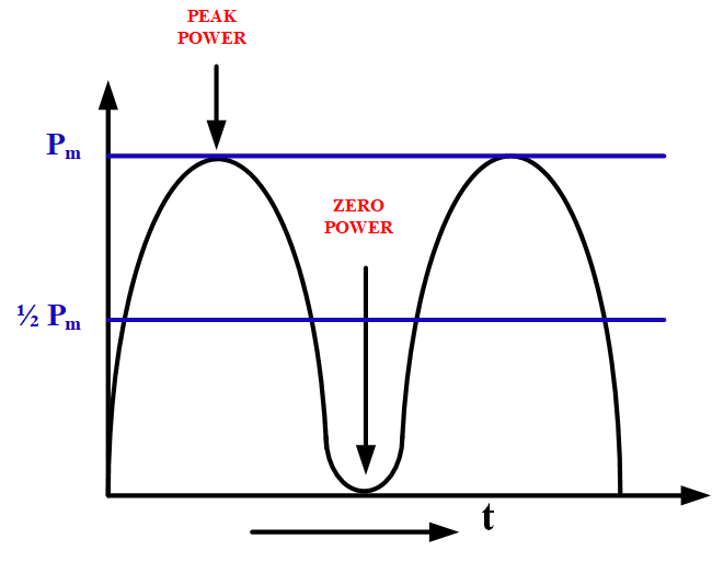
Fig.1: The average power dissipated in a resistor is half the peak power
If the resistance were the tungsten filament of a lamp, and if the frequency of the alternating current is 0.1 Hz, the filament could easily be seen to go bright and dim at a frequency of 0.2 Hz. The lamp would be bright when the current is +Im, dim when the current is zero, and bright again when the current is –Im.
The waveform of power in figure 1 shows that two positive peaks of power occur during each cycle of current. As the normal domestic and industrial power frequency is 60 Hz (in North America), any fluctuations in the brightness of an electric lamp are much too fast for the human eye to detect.
Example 1
A 100-W electric lamp is supplied from a 115 V, 60 Hz source, as in figure 2. Calculate:
(A). the level of current that flows
(B). the resistance of the filament
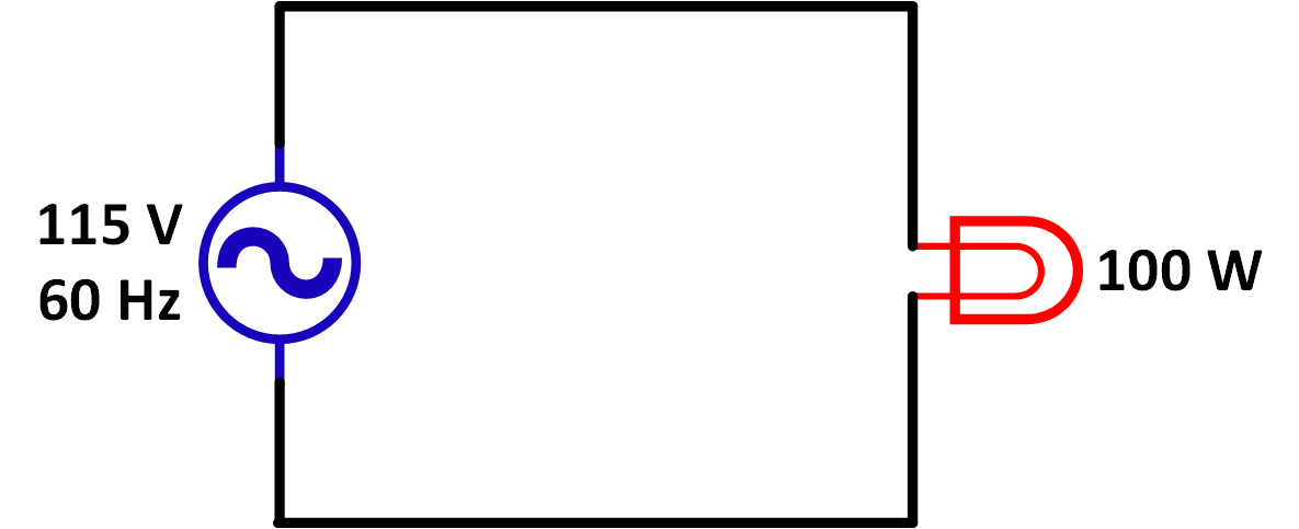
Fig.2: The average power dissipated in a lamp with an AC supply depends on the RMS levels of the voltage and current
Solution
- Equation (1)
$P=EI$
Therefore,
\[I=\frac{P}{E}=\frac{100}{115}=870mA\]
- Equation (2)
\[P=\frac{{{E}^{2}}}{R}\]
Or
\[R=\frac{{{E}^{2}}}{P}=\frac{{{115}^{2}}}{100}=132\Omega \]
Power in an Inductance
When an alternating voltage is applied to a pure inductance, the current lags the applied voltage by 90o. The waveforms of current and voltage for an inductance are shown in figure 3. Because the instantaneous power supplied to any component is calculated as
$p=e\times i$
The waveform of power can easily be derived from the current and voltage waves.

Fig.3: the waveform of power supplied from an AC source to a pure inductance can be derived from the voltage and the current waveforms (using instantaneous levels, p=ei). The average power absorbed by the inductance is zero.
At time t1, on figure 3,
$\begin{matrix} i=0 & and & e={{E}_{m}} \\\end{matrix}$
Therefore;
$p=i\times {{E}_{m}}=0\times {{E}_{m}}=0$
At t2,
$i={{I}_{m}}\sin {{45}^{o}}$
\[i=\frac{{{I}_{m}}}{\sqrt{2}}=I(rms\text{ }value)\]
And
$e={{E}_{m}}\sin {{135}^{o}}$
\[e=\frac{{{E}_{m}}}{\sqrt{2}}=E(rms\text{ }value)\]
Therefore,
${{p}_{m}}=IE$
At t3,
$\begin{matrix} i={{I}_{m}} & and & e=0 \\\end{matrix}$
So
$p={{I}_{m}}\times 0=0$
At t4,
\[\begin{matrix} i=\frac{{{I}_{m}}}{\sqrt{2}} & and & e= \\\end{matrix}-\frac{{{E}_{m}}}{\sqrt{2}}\]
Giving,
\[{{p}_{m}}=\left[ \frac{{{I}_{m}}}{\sqrt{2}} \right]\times \left[ -\frac{{{E}_{m}}}{\sqrt{2}} \right]=-IE\]
At this point (when p=-IE) the power supplied is a negative quantity, which means that the inductance is not absorbing power but supplying power. Continuing the process of calculating and plotting the instantaneous power levels in figure 3, it is seen that the frequency of the power waveform is twice the voltage and current frequency. Also, because the negative half cycles of power supplied are equal to the positive half cycles, the average power supplied to the inductance is zero.
Energy can be stored in an inductor. Therefore, referring to figure 3, it can be said that the energy supplied to the inductor is stored during the time that energy input is a positive quantity and that the stored energy is returned to the source if supply when the energy input is negative.
Example 2
A 30 mA current is measured in a pure inductance connected to a 50 V AC source. Calculate the peak positive and peak negative power dissipation.
Solution
${{E}_{m}}=\sqrt{2}\times 50=70.7V$
${{I}_{m}}=\sqrt{2}\times 30mA=42.43mA$
From the waveform in figure 2:
$peak\text{ }positive\text{ }power\text{ }dissipation,{{P}_{+}}=\left( 70.7\times \sin {{135}^{o}} \right)\times \left( 42.43\times \sin {{45}^{o}} \right)=1.5W$
$peak\text{ }negative\text{ }power\text{ }dissipation,{{P}_{-}}=\left( 70.7\times \sin ({{135}^{o}}+{{90}^{o}}) \right)\times \left( 42.43\times \sin ({{45}^{o}}+{{90}^{o}}) \right)=-1.5W$
Power in a Capacitance
In the case of a pure capacitance supplied with an alternating voltage, the current leads the voltage by 90o. Figure 4 shows the current and voltage waveforms for a capacitance and the waveform of power supplied, as derived from the current and voltage waves.
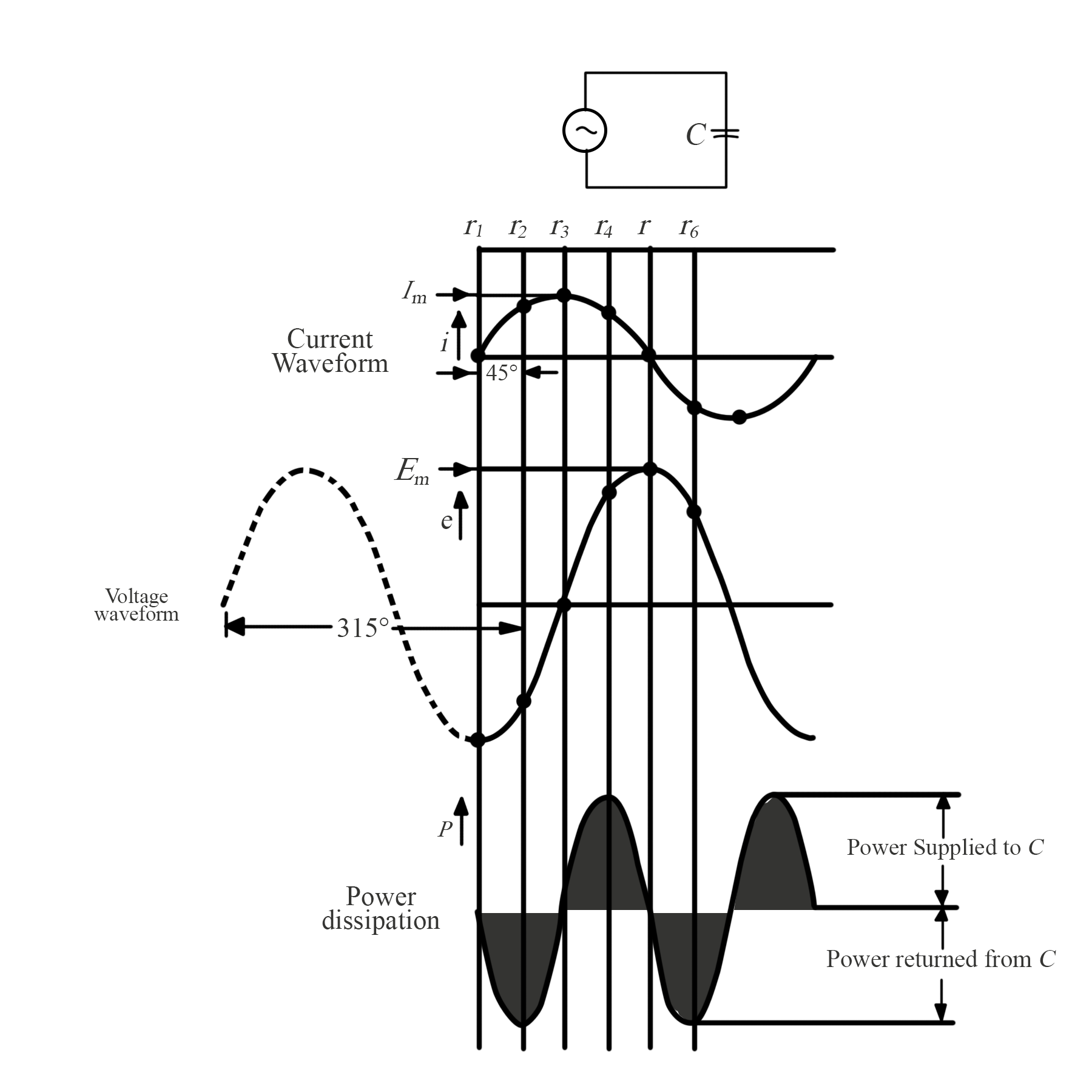
Fig.4: The waveform of power supplied from an AC source to a pure capacitance can be derived from the voltage and the current waveforms (using instantaneous levels, p=ei). The average power absorbed by the capacitance is zero.
At t1,
$p=i\times e=0\times (-{{E}_{m}})=0$
At t2,
$i={{I}_{m}}\sin {{45}^{o}}$
\[i=\frac{{{I}_{m}}}{\sqrt{2}}=I(rms\text{ }value)\]
And
$e={{E}_{m}}\sin {{315}^{o}}$
\[e=-\frac{{{E}_{m}}}{\sqrt{2}}=-E(rms\text{ }value)\]
Therefore,
${{p}_{m}}=-IE$
Continuing the process, exactly as was done for the inductive circuit, it is seen that the frequency of the waveform of power supplied to a capacitor is twice that of the voltage and current frequency. It is also seen that the power supplied to the capacitor is alternatively positive and negative, meaning that the capacitor stores the power supplied to it then returns the stored power to the source of supply. The result of this is that the average power supplied to the capacitance is zero.
Example 3
For the circuit and the waveforms illustrated in figure 4, Im=100mA and Em=25V. Calculate the instantaneous power supplied to the capacitor at a time halfway between t2 and t3.
Solution
Phase angle for i,
\[\theta ={{45}^{o}}+{}^{{{45}^{o}}}/{}_{2}={{67.5}^{o}}\]
Phase angle for e,
\[\phi ={{315}^{o}}+{}^{{{45}^{o}}}/{}_{2}={{337.5}^{o}}\]
$i={{I}_{m}}\sin {{67.5}^{o}}=100mA\times \sin {{67.5}^{o}}=92.4mA$
$e={{E}_{m}}\sin {{337.5}^{o}}=25\times \sin {{337.5}^{o}}=-9.6V$
$p=e\times i=-9.6\times 92.4=-884mW$