Definition: The response of current and voltage in a circuit immediately after a change in applied voltage is called the transient response.
Refer to Figure 1. A capacitor and a resistor are connected in series across a voltage source. A circuit that contains resistance and capacitance is called an RC circuit.
When the switch is closed in this RC circuit, the maximum current will flow. The current gradually decreases until the capacitor has reached its full charge. The capacitor will charge to the level of the applied voltage.

Figure 1. This series RC circuit demonstrates the transient response of a capacitor.
Initially, however, the voltage across the capacitor is zero. When the switch is closed, the voltage across the capacitor gradually builds up to the value of the source voltage. This charging of the capacitor is shown in Figure 2.
The current in the RC circuit is also shown in this figure. Notice that when the switch is closed, the current rises to a maximum almost immediately. The current falls as the capacitor charges. When the capacitor reaches a full charge, the current is zero.
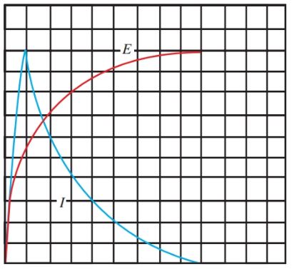
Figure 2. Current and voltage in the series RC circuit.
When the switch is opened, the capacitor remains charged. Theoretically, it would remain charged indefinitely, but there is always some leakage through the dielectric. After some period of time, the capacitor will discharge itself.
In Figure 3, the series combination of a charged capacitor and resistor are short-circuited by providing a discharge path. Because there is no opposing voltage, the discharge current will instantly rise to maximum and gradually fall off to zero.
The combined graph of the charge and discharge of the capacitor is shown in Figure 4.
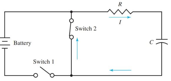
Figure 3. A short circuit occurs in the RC circuit when Switch 2 is closed.
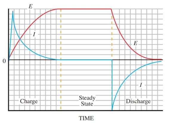
Figure 4. This combination graph shows the rise and decay of current and voltage in the series RC circuit.
Voltages appear across the resistor and capacitor in this circuit. The voltage across R is a result of the current, E = IR. Thus, the maximum voltage appears across R when the maximum current is flowing. This condition exists immediately after the switch is closed in Figure 1, and after the discharge, the switch is closed in Figure 3.
In both cases, the voltage across R drops off or decays as the capacitor approaches full charge or discharge. The graph of the voltage across R is drawn in Figure 5.
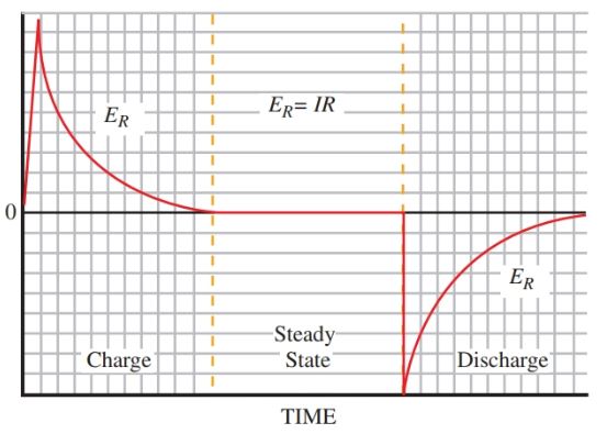
Figure 5. This graph shows the voltage drop across R as the capacitor is charged and discharged.
RC Time Constant
During the charge and discharge of the series RC network outlined above, a period of time elapsed. This time is indicated along the base, or x-axis, of the graphs in Figure 4 and 5.
The amount of time needed for the capacitor to charge or discharge 63.2 percent is known as the time constant of the circuit.
The formula to determine the time constant in RC circuits is:
$\tau =RC$
Where τ is the time constant in seconds, R is the resistance in ohms, and C is the capacitance in farads. For complete charge or discharge, five-time constant periods are required. Assuming a source voltage equal to 100 volts, Figure 6 shows the time constant, percentage, and voltage.
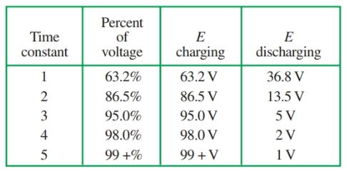
Figure 6. A source voltage of 100 volts will create the time constant, percentage, and voltage shown.
RC Time Constant Calculation Example
A 0.1 microfarad capacitor is connected in series with a one megohms (1,000,000 ohms) resistor across a 100-volt source. How much time will elapse during the charging of C?
$\tau =(0.1*{{10}^{-6}})*({{10}^{6}})=0.1s$
One-tenth of a second is the time constant. This means that C would charge to 63.2 volts during 0.1 seconds. At the end of five-time constants, or 5 × 0.1 = 0.5 seconds, the capacitor is fully charged.
- You May Also Read: RC Series Circuit Analysis | RC Time Constant
Set up the circuit in Figure 7. This neon lamp will remain unlit until a certain voltage level is reached. At the required voltage, called the ignition, or firing voltage, the lamp glows and offers little resistance in the circuit.
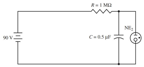
Figure 7. This flashing circuit is called a relaxation oscillator.
In this circuit, capacitor C charges through resistance R. When the voltage across C develops to the ignition voltage, the lamp glows. C is quickly discharged. This cycle repeats over and over, causing the neon light to flash.
The frequency of the flashes can be changed by varying either the value of C or R. A telephone with a neon accent is shown in Figure 8.

Figure 8. Neon lights are used in many new products. Here, a neon light highlights this designer phone.
Time constants have many uses in electronic circuits. Timing circuits are used in industry to control the sequence and duration of machine operations. A photographic enlarger uses a time delay circuit to control the exposure time.