This guide covers Series RC Circuit Analysis, its Phasor Diagram, Power & Impedance Triangle, and several solved examples.
Recall that current and voltage are in phase for purely resistive AC circuits, while current leads voltage by 90 degrees in purely capacitive circuits. Therefore, when resistance and capacitance are combined, the overall difference in angle between circuit voltage and current is an angular difference between 0 and 90 degrees.
The combination of a resistor and capacitor connected in series to an AC source is called a series RC circuit. Figure 1 shows a resistor and pure or ideal capacitor connected in series with an AC voltage source.
The current flow in the circuit causes voltage drops to be produced across the capacitor and the resistor. These voltages are proportional to the current in the circuit and the individual resistance and capacitor values. The resistor voltage (ER) and the capacitor voltage (EC) expressed in terms of Ohm’s law are
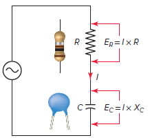
Figure 1 Series RC circuit diagram

Series RC circuits are similar to series RL circuits. The formulas are basically the same with capacitance values substituted for inductance values.
In a series RC circuit, the total opposition or impedance is due to a combination of both resistance (R) and capacitive reactance (XC). The formula for the impedance of a series RC circuit based on Ohm’s law remains as

RC Series Circuit Characteristics
The relationship between the current and voltages in a series RC circuit is illustrated in the vector (phasor) diagram of Figure 2 and can be summarized as follows:
- The applied source voltage and current will be out of phase by some amount between 0 and 90 degrees.
- The size of the phase angle will be determined by the ratio between resistance and capacitance.
- The series RC circuit vector is similar to the RL circuit in that it uses the common current element as the reference vector.
- As the frequency increases, the capacitive reactance (XC) decreases, which causes the phase angle, or shift between the applied voltage and current, to decrease.
- For a capacitor, the current I leads the voltage E by 90 degrees; therefore, the only change made is that the capacitor voltage EC lags the current I by 90 degrees and is drawn lagging the current vector by 90 degrees.
- The total supply voltage (ET) is the vector sum of the resistor and capacitor voltages:
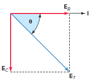
Figure 2 Series RC circuit vector (phasor) diagram.
![]()
Series RC circuit Impedance Triangle and Formula
The resistance (R) and capacitive reactance (XC) are 90 degrees out of phase with each other, and this forms the impedance triangle shown in Figure 3. Once again, the impedance triangle is geometrically similar to the circuit vector diagram and will have the same phase angle theta (θ).
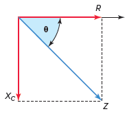
Figure 3 Series RC circuit impedance triangle.
When the resistance and capacitive reactance of a series RC circuit are known, the impedance is found using the equation:
![]()
Impedance Calculation in RC Series Circuit Example 1
An AC series RC circuit is made up of a resistor that has a resistance value of 20 Ω and a capacitor that has a capacitive reactance value of 30 Ω. Calculate the impedance and the phase angle theta (θ) of the circuit.
Solution:
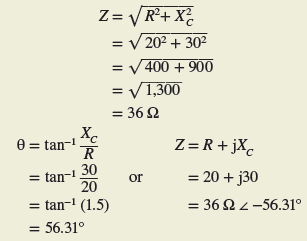
Therefore, the circuit can be said to have a total impedance of 36 Ω ∠−56.31° (relative to the circuit current).
Once the impedance is known, the current and voltage drops can be determined as outlined in example 2. Note that the equations used are basically the same as that used for the series RL circuit with the capacitive component values used in place of the inductive values.
One difference is that the current will be in phase with the resistance voltage drop, ER, but will lead the capacitance voltage drop, EC, by 90 degrees.
Series RC Circuit Calculation Example 2
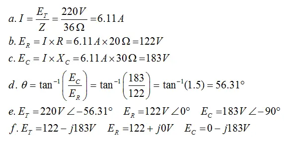
For the series RC circuit shown in Figure 4:
- Calculate the value of the current flow.
- Calculate the value of the voltage drop across the resistor.
- Calculate the value of the voltage drop across the capacitor.
- Calculate the circuit phase angle based on the voltage drops across the resistor and capacitor.
- Express all voltages in polar notation.
- Use a calculator to convert all voltages to rectangular notation.
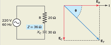
Figure 4 RC Series Circuit for example 2.
Solution:
Like RL circuits, RC circuits have significant values of apparent power, reactive power, and true power. True power (watts) is found in the resistive part of the circuit. Capacitive reactive power (VARs) is found in the capacitive part of the circuit. The total or apparent power (VA) will contain both a true power component and a reactive power component.
The power equations for a series RC circuit are similar to those for series RL circuits and are calculated as shown in example 3.
Power Calculation in RC Series Circuit Example 3
For the series RC circuit shown in Figure 5, determine:
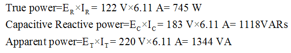
- True power.
- Capacitive reactive power.
- Apparent power.
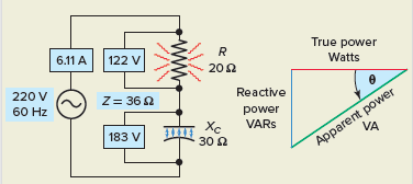
Figure 5 Circuit for example 3.
Solution:
Recall the power factor of any AC circuit is equal to the ratio of the true power to apparent power:
RC Series Circuit Power Factor
In a series RL circuit it was shown that the current lags the applied voltage and the power factor and, in this case, is described as lagging. For a series RC circuit, the current leads the applied voltage and the power factor is described as leading.
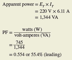
Power Factor for RC Series Circuit Example 4
Determine the power factor for the series RC circuit shown in Figure 6.
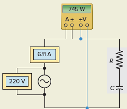
Figure 6 Circuit for example 4.
Solution:
Capacitive Reactance in RC Circuit Example 5
For the series RC circuit shown in Figure 7, determine:
- Capacitive reactance (XC).
- Impedance (Z).
- Current (I).
- Voltage drop across the resistor (ER) and capacitor (EC).
- The angle theta (θ) and power factor (PF) for the circuit.
- True power (W), reactive power (VARs), apparent power (VA).
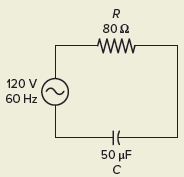
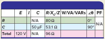
Figure 7 Circuit for example 5.
Solution:
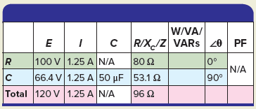
Step 1. Make a table and record all known values.
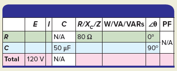
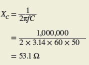
Step 2. Calculate XC and enter the value in the table.
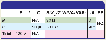
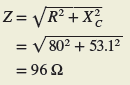
Step 3. Calculate Z and enter the value in the table.
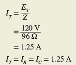
Step 4. Calculate IT, IR, and IC and enter the values in the table.
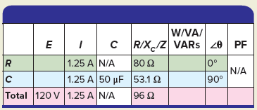
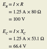
Step 5. Calculate ER and EC and enter the values in the table.
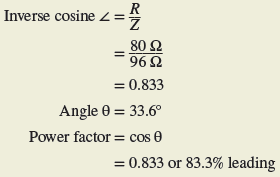
Step 6. Calculate the angle θ and PF for the circuit and enter the values in the table.
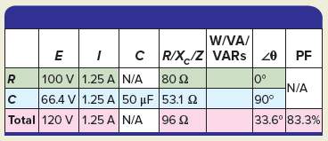
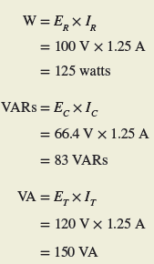
Step 7. Calculate the W, VARs, and VA for the circuit and enter the values in the table.
It is impossible to have a pure AC capacitance because all capacitors will have a certain amount of internal resistance across their plates, giving rise to a leakage current. When the capacitor resistance is to be taken into consideration, then we need to represent the total impedance of the capacitor as a resistance in series with a capacitance.
Review Questions
1. For the series RC circuit shown in Figure 8:
- Calculate the value of the applied voltage.
- Determine the angle displacement theta (θ) by which the current leads the applied voltage.
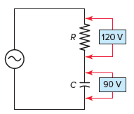
Figure 8 Circuit for review question 1.
2. Determine the value of the current flow for the series RC circuit of Figure 9. Show all steps required to arrive at the answer.
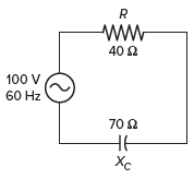
Figure 9 Circuit for review question 2.
3. The known quantities in a given series RC circuit are as follows: Resistance equals 30 Ω, capacitive reactance equals 40 Ω, and the applied voltage is 200 volts, 60 Hz. Determine the following unknown quantities:
- Impedance.
- Voltage across the resistor.
- Voltage across the capacitor.
- Angle by which the current leads the applied voltage.
- Circuit power factor.
4. For the circuit of Figure 10, determine:
- Wattmeter reading.
- ER.
- EC.
- Apparent power.
- Reactive power.
- Power factor.
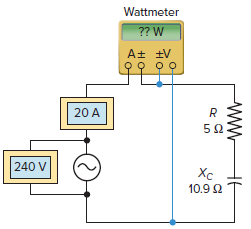
Figure 10 Circuit for review question 4.
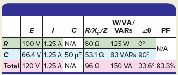
5. Complete a table for all given and unknown quantities for the series RC circuit shown in Figure 11.
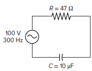
Figure 11 Circuit for review question 5.
Review Questions – Answers
- (a) 150 V, (b) 36.87°
- Z= 81 Ω, I = 1.23 A
- (a) 50 Ω, (b) 120 V, (c) 160 V, (d) 53.13°, (e) 0.6 or 60 %
- (a) 2000 W, (b) 100 V, (c) 218 V, (d) 4800 VA, (e) 4360 VARs, (f) 0.417 or 41.7% leading
| E | I | C | R /XC /Z | W/ VA /VARs | PF | ||
| R | 66.3 V | 1.41A | N/A | 47 Ω | 93.4 W | 0 | N/A |
| C | 74.9 V | 1.41A | 10F | 53.1 Ω | 106 VARs | 90 | |
| Total | 100 V | 1.41A | N/A | 70.9 Ω | 141 VA | 48.5 | 66.2% |