This article examines the resonance phenomenon and resonance frequency in series and parallel RLC circuits, along with several examples.
In any AC circuit consisting of resistors, capacitors, and inductors, either in series or in parallel, a condition can happen in which the reactive power of the capacitors and of the inductors become equal. This condition is called resonance.
Simultaneous with the capacitive reactive power and the inductive reactive power being equal, other features can reflect resonance. Remember that we always reduce a circuit to a single resistor, a capacitor, and an inductor. Thus, for this discussion, we assume one of each component in the circuit.
Resonance: a Special condition in AC circuits where all the energy stored by inductive components is provided by capacitive components, and vice versa. This occurs in a particular frequency. This condition implies other facts such as:
- The net reactive power to be zero,
- The power factor to be unity, and
In fact, when resonance happens, the inductive reactance and the capacitive reactance are equal to each other:
$\begin{matrix} {{X}_{L}}={{X}_{C}} & {} & \left( 1 \right) \\\end{matrix}$
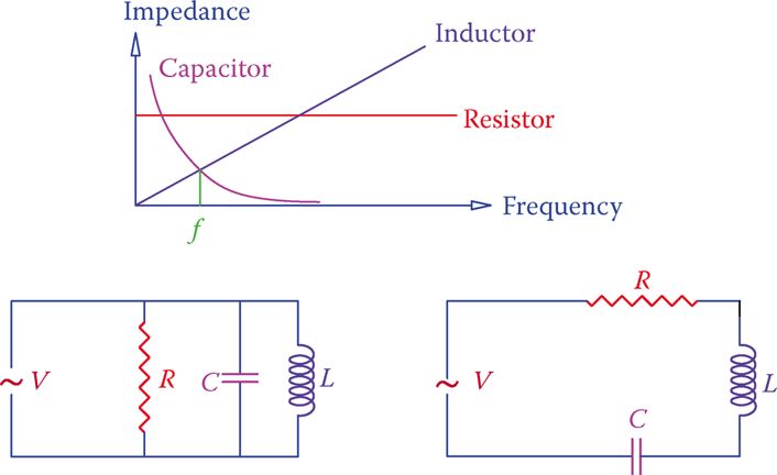
Figure 1. Resonance condition in Series and Parallel AC circuits.
In a circuit with a fixed frequency, resonance can happen if the condition in Equation 1 is true.
On the other hand, since both XL and XC are functions of frequency, if the frequency of a circuit changes, at a unique frequency these values can become equal.
Figure 1 shows the variation of the impedance for the three basic types of loads in a circuit versus frequency. The horizontal axis implies a frequency increase.
A resistor is independent of frequency; thus, its impedance is constant, represented by a line parallel to the horizontal axis.
The impedance of an inductor is proportional to the frequency and augments as the frequency increases. For a capacitor the reverse happens and its impedance decreases (though not linearly) as the frequency increases.
At the point of intersection of the two curves, XL = XC, and the frequency at that point is called the resonant frequency or resonance frequency and is denoted by fR.
Resonant frequency: A unique frequency for each AC circuit containing both reactive components (inductors and capacitors) at which the resultant reactance of all capacitive components is equal to the resultant reactance of all the inductive components. As a result, the two types of components cancel the effect of each other, and the total reactive power of the circuit is zero.
Resonance frequency: Frequency at which resonance happens in an AC circuit.
The resonance frequency can be found by equating XL and XC. This leads to
\[\begin{matrix} {{f}_{R}}=\frac{1}{2\pi \sqrt{LC}} & {} & \left( 2 \right) \\\end{matrix}\]
Resonance Frequency Calculation Example 1
Find the resonance frequency of a 40 mH inductor and a 51 μF capacitor.
Solution
Values of the capacitance and inductance in Farad and Henry can directly be plugged in Equation 2. Thus,
\[{{f}_{R}}=\frac{1}{2\pi \sqrt{LC}}=\frac{1}{2\pi \sqrt{0.040*0.00051}}=112Hz\]
Resonance Frequency Calculation Example 2
Find the capacitance for a capacitor to become in resonance with a 40 mH inductor at 60 Hz frequency.
Solution
At 60 Hz the reactance of the capacitor must be the same as the reactance of the inductor. Thus,
$\begin{align} & {{X}_{C}}={{X}_{L}}=2\pi *60*0.040=15\Omega \\ & C=\frac{1}{2\pi *60*15}=176mF \\\end{align}$
Note that if this value is not among the standard values for capacitors, one can make such a value by combining a number of standard capacitors in series and/or parallel.
Resonance in Series RLC Circuits
When resonance occurs in a series RLC circuit, the resonance condition (Equation 1) leads to other relationships or properties. These are
- The voltage across the inductor is equal to the voltage across the capacitor.
- The voltage across the resistor is equal to the applied voltage.
- The impedance of the circuit has its lowest value and is equal to R.
- Circuit current assumes its maximum value because the impedance is minimum.
- The power factor for the circuit becomes equal to 1, and the phase angle is zero.
- Apparent power has its lowest value and becomes equal to the active power because the power factor is 1.
Resonance in Parallel RLC Circuits
Similar to the series circuits, when resonance occurs in a parallel RLC circuit the resonance condition (Equation 1) leads to other relationships or properties:
- The current in the inductor is equal to the current in the capacitor.
- The current in the resistor is equal to the total circuit current.
- The impedance of the circuit has its highest value and is equal to R.
- Circuit current assumes its minimum value because the impedance has the highest value.
- The power factor for the circuit becomes equal to 1, and the phase angle is zero.
- Apparent power has its lowest value and becomes equal to the active power because the power factor is 1.
Items 5 and 6 are the same as for the series resonant circuits, but the rest are quite different.
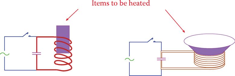
Figure 2. Principle of induction heater and induction cooker.
When resonance occurs in a parallel RLC circuit, a local current circulates between the inductor and the capacitor. This current can be very high, while the circuit current as seen from the source can be low. This phenomenon is used in induction heaters (in the industry for heating metals when necessary, e.g., heating bearings for mounting or dismounting) and in induction cookers (for domestic use).
In such an application a high current is flowing through an inductor, whereas the current provided by the power line is small. This means that the rating of the wires and breakers is much smaller than the current in the inductor.
The current in the inductor creates (induces) local currents in the piece to be warmed, without even touching it. In the case of an induction cooker, the body of the cooking pan becomes hot owing to local currents created by induction. This is shown in Figure 2.
The efficiency of induction heating is very high, and the process is very fast compared to conventional heating in which a great part of the energy is used for heating air and the intermediate media between the source and the body to be heated.