This guide covers RL Series Circuit Analysis, its Phasor Diagram, Power & Impedance Triangle, and several solved examples.
In a purely resistive AC circuit, any inductive effects are considered negligible. Similarly, in a purely inductive AC circuit, any resistive effects are considered extremely small, and as a result they are omitted from any calculations. In many AC circuits, however, the load is actually a combination of both resistance and inductance. That is, the circuit can no longer be treated as either purely resistive or as purely inductive.
RL Series Circuit
The combination of a resistor and inductor connected in series to an AC source is called an RL Series Circuit. Figure 1 shows a resistor and a pure or ideal inductor connected in series with an AC voltage source.
The current flow in the circuit causes voltage drops to be produced across the inductor and the resistor. These voltages are proportional to the current in the circuit and the individual resistance and inductive reactance values.
As in any series circuit, the current will be the same value throughout the circuit. The resistor voltage (ER) and the inductor voltage (EL) expressed in terms of Ohm’s law are
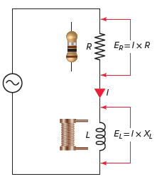
Figure 1 RL Series circuit diagram

The total opposition to current flow in any AC circuit is called impedance. In a series RL circuit, this total opposition is due to a combination of both resistance (R) and inductive reactance (XL). The symbol for impedance is Z, and like resistance and reactance, it too is measured in ohms.
From Ohm’s law, the impedance of a circuit will be equal to the total supply voltage (ET) divided by the circuit current:
![]()
It was previously shown that the current flowing through a pure resistance was in phase with the voltage across the resistance and that the current through a pure inductance lagged the voltage across the inductance by 90 degrees. For this reason, in the series RL circuit, the two voltage drops will not be directly additive but will be a vector sum.
RL Series Circuit Phasor (Vector) Diagram
The relationship between the current and voltages in a series RL circuit is shown in the vector (phasor) diagram of Figure 2 and can be summarized as follows:
- The reference vector is labeled I and represents the current in the circuit, which is common to all circuit elements.
- Since the voltage across the resistor is in phase with the current flowing through it, the voltage vector ER, it is drawn superimposed on the current vector.
- The inductor voltage EL leads the current by 90 degrees and is drawn leading the current vector by 90 degrees.
- The total supply voltage (ET) is the vector sum of the resistor and inductor voltages:
![]()
- The phase shift between the applied voltage and current is between 0 and 90 degrees.
- As the frequency increases, the inductive reactance (XL) increases, which causes the phase angle, or shift between the applied voltage and current, to increase.
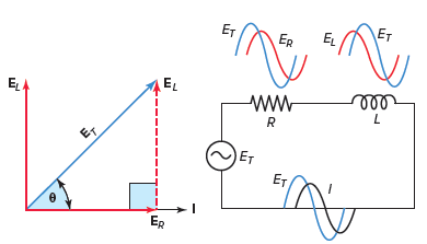
Figure 2 RL Series circuit vector (phasor) diagram.
Due to the phase shift created by the inductor, the impedance of an RL series circuit cannot be found by simply adding the resistance and inductive reactance values. The total impedance of a series RL circuit, similar to its total voltage, is the vector sum of the resistance and inductive reactance.
RL Series Circuit Impedance Triangle
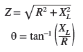
The impedance triangle for a series RL circuit is shown in Figure 3. Note that the impedance triangle is geometrically similar to the circuit vector diagram and will have the same phase angle theta (θ). The reason for this is that the voltage drops for the resistor and the inductor are a result of the current flow in the circuit and their respective opposition. Equations used to solve the impedance triangle include:
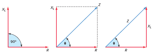
Figure 3 RL Series circuit Impedance triangle.
Impedance Calculation in RL Series Circuit Example 1
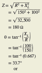
Problem: An AC series RL circuit is made up of a resistor that has a resistance value of 150 Ω and an inductor that has an inductive reactance value of 100 Ω. Calculate the impedance and the phase angle theta (θ) of the circuit.
Solution:
Once the impedance of a circuit is found, it is possible to find the current by using Ohm’s law and substituting Z for R as follows:

Since the current is the same throughout the series circuit, the individual voltage drops across the inductor and resistor can be calculated by applying Ohm’s law as follows:

RL Series Circuit Calculations Example 2
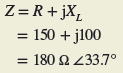
Problem: For the RL series circuit shown in Figure 4:
- Calculate the value of the current flow.
- Calculate the value of the voltage drop across the resistor.
- Calculate the value of the voltage drop across the inductor.
- Calculate the circuit phase angle based on the voltage drops across the resistor and inductor.
- Express all voltages in polar notation.
- Use a calculator to convert all voltages to rectangular notation.
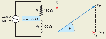
Figure 4 RL series circuit for Example 2.
Solution:
Power in an RL Series Circuit
The various power components associated with the RL series circuit are shown in Figure 5 and can be identified as follows:
- True power is measured in watts (W) and is the power drawn by the resistive component of the circuit. For a pure resistor, the voltage and current are in phase, and power dissipated as heat is calculated by multiplying voltage by current (W=ER× IR).
- Reactive power is measured in volt-amperes reactive (VARs). Reactive power is the power continually stored and discharged by the magnetic field of the inductive load. For purely inductive loads, the voltage and current are 90 degrees out of phase, and the true power in watts is zero. The inductive reactive power is calculated by multiplying the inductor voltage by its current (VARs=EL×IL)
- Apparent power is measured in volt-amperes (VA) and is the combination of reactive and true power. For an RL series circuit, the phase shift between the applied voltage and current is between 0 and 90 degrees. The apparent power or volt-amps is calculated by multiplying the applied voltage by the current flow (VA=ET×IT).
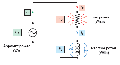
Figure 5 Power components associated with the RL series circuit.
RL Series Circuit Power Triangle
The power triangle of Figure 6 shows the relationship between the various power components of a series RL circuit. In this triangle:
- The length of the hypotenuse of a right-angle triangle represents the apparent power.
- The angle theta (θ) is used to represent the phase difference.
- The side adjacent to theta (θ) represents the true power.
- The side opposite theta (θ) represents the reactive power.
- The power triangle is geometrically similar to the impedance triangle and the series RL circuit vector diagram.
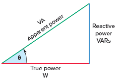
Figure 6 RL series circuit power triangle.
Power Calculations in RL Series Circuit Example 3
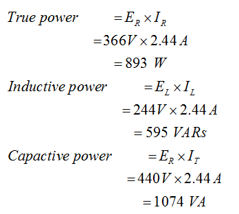
Problem: For the series RL circuit shown in Figure 7, determine:
- True power.
- Inductive reactive power.
- Apparent power.
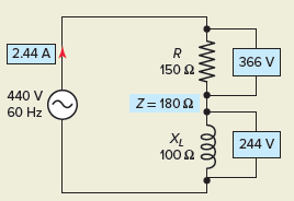
Figure 7 RL series circuit for Example 3.
Solution:
RL Series Circuit Power Factor
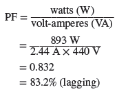
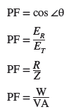
The power factor (PF) for any AC circuit is the ratio of the true power (also called real power) to the apparent power:
![]()
Power factor is a measure of how effectively equipment converts electric current to useful power output, such as heat, light, or mechanical motion. The power factor for an RL series circuit is the ratio of the actual power dissipation to apparent power and can be summarized as follows:
- The power factor ranges from 0 to 1 and is sometimes expressed as a percentage.
- A 0 percent PF indicates a purely reactive load, while a 100 percent PF indicates a purely resistive load.
- For circuits containing both resistance and inductive reactance, the power factor is said to be lagging (current lags) in some value between 0 and 1.
- The greater the power factor, the more resistive the circuit; the lower the power factor, the more reactive the circuit.
- Circuit power factor is an indication of the portion of volt-amperes that are actually true power; a high PF indicates a high percentage of the total power is true power.
For many practical applications, the power factor of a circuit is determined by metering total circuit voltage, current, and power, as illustrated in the circuit of Figure 8. The power factor can then be determined by dividing the reading of the wattmeter by the product of the voltmeter and ammeter readings as follows:
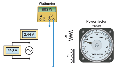
Figure 8 Find RL series circuit power factor.
The power factor is not an angular measure but a numerical ratio with a value between 0 and 1. As the phase angle between the source voltage and current increases, the power factor decreases, indicating an increasingly reactive circuit. Any of the following equations can be used to calculate the power factor of a series RL circuit:
RL Series Circuit Example 4
Problem: For the RL series circuit shown in Figure 9, determine:
- Inductive reactance (XL).
- Impedance (Z).
- Current (I).
- Voltage drop across the resistor (ER) and inductor (EL).
- The angle theta (θ) and power factor (PF) for the circuit.
- True power (W), reactive power (VARs), apparent power (VA).
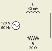
Figure 9 RL Circuit for Example 4.
Solution:
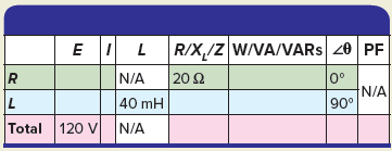
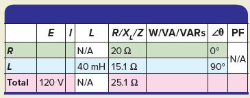
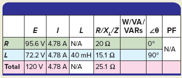
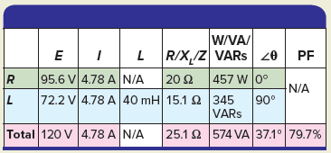
- Step 1. Make a table and record all known values.
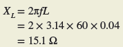
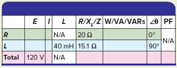
Step 2. Calculate XL and enter the value in the table.
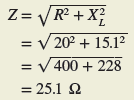
Step 3. Calculate Z and enter the value in the table.
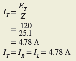
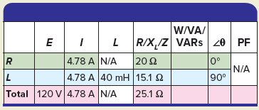
Step 4. Calculate IT, IR, and IL and enter the values in the table.
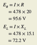
Step 5. Calculate ER and EL and enter the values in the table.
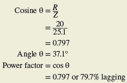
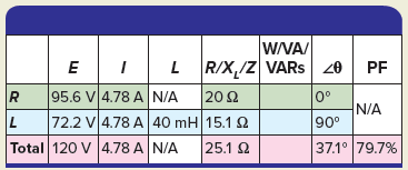
Step 6. Calculate the angle θ and PF for the circuit and enter the values in the table.
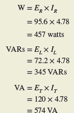
Step 7. Calculate the W, VARs, and VA for the circuit and enter the values in the table.
A real inductor has resistance due to the wire. It is impossible to have a pure inductance because all coils, relays, or solenoids will have a certain amount of resistance, no matter how small, associated with the coils turns of wire being used. This being the case, we can consider our simple coil as being a resistance in series with a pure inductance.
RL Series Circuit Review Questions
- Define the term impedance as it applies to AC circuits.
- What symbol is used to represent impedance?
- A circuit consists of a resistance of 20 Ω and an inductive reactance of 40 Ω connected in series and supplied from a 240-volt, 60-Hz source. Determine:
- The circuit impedance.
- Amount of current flow.
- The phase angle theta (θ) of the circuit.
- For the series RL circuit vector (phasor) diagram shown in Figure 10, determine the value of the voltage drop across the inductor.
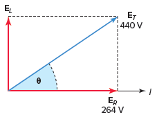
Figure 10 Vector for a review question 4.
5. The known quantities in a given RL series circuit are as follows: Resistance equals 8 Ω, inductive reactance equals 39 Ω, current equals 3 A, and the applied voltage is 120 volts, 60 Hz. Determine the following unknown quantities:
- Impedance.
- Voltage across the resistor.
- Voltage across the inductor.
- Angle by which the applied voltage leads the current.
6. A wattmeter connected to a 240-volt, 60-Hz series RL circuit indicates a reading of 691 watts. A clamp-on ammeter used to measure current flow indicates a current of 4.8 A. Determine the:
- True power.
- Apparent power.
- Reactive power.
- Circuit power factor.
7. For the series RL circuit shown in Figure 11, determine:
- Apparent power.
- True power.
- Reactive power.
- Circuit power factor.
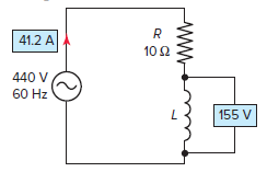
Figure 11 RL Series Circuit for a review question 7.
8. Complete a table for all given and unknown quantities for the series RL circuit shown in Figure 12.
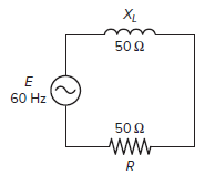
Figure 12 Series RL Circuit for a review question 8.
9. The frequency of an RL series circuit is decreased. What effect will this have on the phase angle between the applied voltage and current? Why?
Review Questions – Answers
- The total opposition offered to the current flow in the AC circuit.
- Z
- (a) 44.7 Ω (b) 5.4 A (c) 63.4°
- 352 V
- (a) 40 Ω (b) 24 V (c) 117 V (d) 78.4 °
- (a) 691 Watts (b) 1152 VA (c) 921.6 VAR (d) 60%
- (a) 18.1 kVA, (b) 17 k Watts, (c) 6,380 VAR, (d) 94%
| E | I | R /XL /Z | W/ VA /VARs | PF | ||
| R | 155 V | 3.1 A | 50 Ω | 480.5 W | 0 | |
| L | 155 V | 3.1 A | 50 Ω | 480.5 VARs | 90 | |
| Total | 220 V | 3.1 A | 70.7 Ω | 682 VA | 45 | 71 % |
9. The inductive reactance (XL) decreases, causing the phase angle between the applied voltage and current to decrease.