There are numerous applications for the principles of series circuits. This section demonstrates how to apply those principles and shows you the specific example of an airfield lighting system. In addition, troubleshooting series circuits is discussed.
Applying Ohm’s Law to a Series Circuit
Ohm’s law can be applied to any individual component of a series circuit. Look at Figure 1. The Ohm’s law formulas are noted at each location. If you know any two values at an individual location, you can apply Ohm’s law to find the third value.
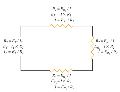
Figure 1. Ohm’s law can be applied at each location in the circuit. Note that when the current value is found, it can be applied anywhere in the circuit.
Example: If R1 has a resistance value of 10 ohms and a voltage drop of five volts, then applying Ohm’s law to the R1 location will give you a current value of 0.5 amperes.
\[{{I}_{1}}=\frac{{{V}_{1}}}{{{R}_{1}}}=\frac{5V}{10\Omega }=0.5A\]
Could you go on from this point and calculate the amount of power used by R1?
Airfield Lighting System
An airfield lighting system has many miles of circuit cable. The system has miles of cable originating from the source of power to the runway, plus the distance around the runway itself.
The only practical way to light a runway and taxiway system is to use the series circuit principles. Figure 2 illustrates how large the system may be. The voltage losses caused by the resistance of the copper lines do not permit a practical application of a parallel circuit.
The lighting consists of a series circuit with a transformer located at each individual light location. The circuit is connected to a voltage regulator that maintains a constant amperage applied to the circuit. Since the circuit has a constant amperage, and each transformer and lighting unit has equal resistance, each lamp will have the same voltage drop value.
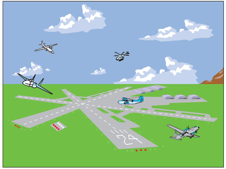
Figure 2. An airport lighting system can be over 50 miles in length for all circuits.
At times, the number of lamps in the circuit will change due to lamp failure. When the number of lamps changes, the amount of applied voltage from the regulator will change in order to maintain the constant 6.6 amperes applied to the circuit.
By maintaining a constant 6.6 amperes to the circuit, each lamp will burn at the same brightness, regardless of how many lamps are lit at once, and regardless of the voltage drop along the length of the conductor. See Figure 3.
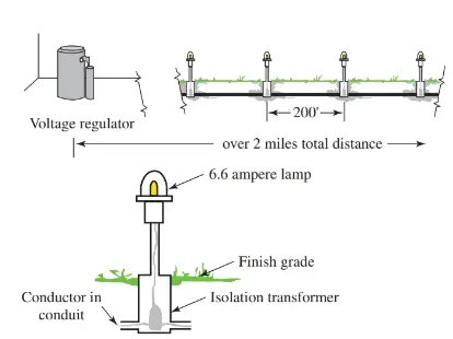
Figure 3. A typical airfield lighting system consists of a series of lamps connected to a voltage regulator. Each lamp will glow at equal brightness
Troubleshooting a Series Circuit Using a Voltmeter
A series circuit is really easy to troubleshoot. In Figure 4, three resistors are connected in series to the power supply. A fuse is used for circuit protection and a SPST switch is used to control the current to the resistors.
One of the most common circuit faults in a series circuit is an open. A voltmeter, combined with the knowledge of the laws of voltages, is a quick and easy method of analysis. There are several ways to locate a circuit fault. The following step-by-step presentation is not the only way to locate the fault.
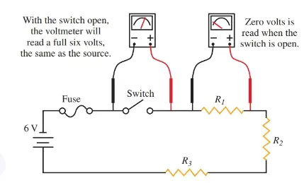
Figure 4. An open switch in a series circuit produces a reading on a voltmeter equal to the source voltage.
Lesson in Safety:
Remember, good safety is a habit that needs to be developed over a period of time. When troubleshooting even low-voltage circuits, practice all safety techniques. Safety must become second nature to a technician when working on electrical circuits.
To begin the troubleshooting process, measure to determine if there is voltage at the supply. Remember, a bad battery can still have a high voltage reading when it is not connected to a load. When checking the battery for proper voltage, make sure the switch (S1) is closed.
If the voltage at the battery is good, move to the fuse. Take a voltage drop reading across the fuse. A good fuse will not produce a voltage drop. A blown fuse will produce a voltage drop that is equal to the source voltage.
Also check the voltage drop across the switch. The closed switch should not produce a voltage drop, Figure 5. A single- pole single-throw (SPST) switch that produces a voltage drop when closed is defective.
Next, check to see if there is a voltage drop across the individual resistors. If a resistor connected in a series circuit is open, it will have a voltage drop equal to the source voltage. The other resistors will have no voltage drop at all.
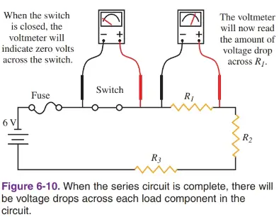
Figure 5. When the series circuit is complete, there will be voltage drops across each load component in the circuit.
A short circuit is another possible problem. If one of the resistors is shorted, that resistor will show a voltage drop of zero. The other resistors in the circuit will drop the entire source voltage.