A capacitor is a passive device which stores energy in an electric field and opposes the change in voltage.
An electric field can be created by placing two conducting plates in parallel and having one plate more positive than other as shown in fig.

The material between two plates is non-conducting or insulating. This insulating material is called dielectric. An example of some dielectrics is air, ceramic, Formica and Teflon.
- You May Also Read: Inductors in Series and Parallel
Capacitance
Capacitance is the property of a capacitor to store energy in an electric field. The energy is stored by the capacitance between parallel plates. The formula for capacitance is;
$C=\frac{Q}{V}$
The unit of capacitance is coulomb per volt, which is defined as farad (F).The farad is the too large unit for practical circuits; Therefore capacitance values are expressed in microfarads (10-6) or pico-Farad (10-18).
It is possible to obtain capacitance expression in terms of dielectric and other physical factors by considering the parallel plates of above figure.A charge is placed on the plates, each having a surface area of A. Then the flux density between the plates is
$D=\frac{Q}{A}\text{ }\cdots \text{ (1)}$
As a consequence of the charge, a voltage V occurs across the capacitor and the field intensity would be;
$\varepsilon =\frac{V}{d}\text{ }\cdots \text{ (2)}$
Whereas absolute permittivity of a dielectric medium would be;
\[\text{ }\!\!\varepsilon\!\!\text{ }~~=\frac{D}{\varepsilon }\text{ }\cdots \text{ (3)}\]
D is the flux density and ε is the electric field intensity. Substituting the preceding expression for D and into equation (3) we find that
$\text{ }\!\!\varepsilon\!\!\text{ }=\frac{D}{\varepsilon }=\left( \frac{Q}{V} \right)\left( \frac{d}{A} \right)$
Q/V is capacitance; so;
\[C=~\text{ }\!\!\varepsilon\!\!\text{ }\frac{A}{d}\text{ }\cdots \text{ (4)}\]
Equation (4) indicates that the capacitance is measured by the geometric factors A and d and by the type of dielectric separating the plates. When the plate area is increased, the capacitance is increased. Similarly, when the separation d is decreased between the plates, the capacitance is increased.
The relative permittivity (εr) is the ratio of the absolute permittivity of a material to that for a vacuum and is defined as;
${{\varepsilon }_{r}}=\frac{\varepsilon }{{{\varepsilon }_{o}}}\text{ }\cdots \text{ (5)}$
The relative permittivity is sometimes called dielectric constant. The dielectric constant for air is 1.0006. Now, substituting the expression of from equation (5) into equation (4), we obtain
$C={{\varepsilon }_{r}}{{\varepsilon }_{o}}~\frac{A}{d}$
Whereas C is in farads and A and d are in the units of square meter and meter, respectively.
Capacitors in Series
In a manner similar to that used for resistors and inductors, let’s apply Kirchhoff’s voltage law to the following figure as an initial step in determining the total capacitance.

${{V}_{T}}={{V}_{1}}+{{V}_{2}}+{{V}_{3}}\text{ }\cdots \text{ (6)}$
As we know that current through capacitor is proportional to rate of change of voltage across the capacitor. Therefore, it is necessary to express both sides of Equation (6) in terms of rate of change of voltage.
$\frac{d{{V}_{T}}}{dt}=\frac{d{{V}_{1}}}{dt}+\frac{d{{V}_{2}}}{dt}+\frac{d{{V}_{3}}}{dt}\text{ }\cdots \text{ (7)}$
Since current flowing through capacitor is given by
\[{{i}_{C}}=C\frac{d{{V}_{c}}}{dt}\]
We may rewrite equation (7) as
\[\frac{{{i}_{T}}}{{{C}_{t}}}=\frac{{{i}_{T}}}{{{C}_{1}}}+\frac{{{i}_{T}}}{{{C}_{2}}}+\frac{{{i}_{T}}}{{{C}_{3}}}\text{ }\cdots \text{ (8)}\]
Dividing both sides of above equation by iT yields;
$\frac{1}{{{C}_{T}}}=\frac{1}{{{C}_{1}}}+\frac{1}{{{C}_{2}}}+\frac{1}{{{C}_{3}}}$
Note that total capacitance for two or more capacitors in series is calculated quite differently from that series resistors and series inductors.
In the case when only two capacitors are connected in series, the equivalent capacitance CT would be,
${{C}_{T}}=\frac{{{C}_{1}}{{C}_{2}}}{{{C}_{1}}+{{C}_{2}}}\text{ }\cdots \text{ (9) }$
Equation (9) is known as a product over sum rule. It may be used only when two capacitors are in series. In case, when two or more series capacitors are equal, the following expression may be used:
${{C}_{T}}=\frac{C}{N}$
Whereas C is the value of one of the equal capacitors and N indicates numbers of capacitors.
Capacitors in Series Example
- What is the total capacitance for a 3 µF capacitor connected in series with a 12 µF capacitor?
First, plug in the capacitor values into the equation. Since both values are µF, so the answer will also be in µF.
CT = (C1 * C2) / (C1 + C2)
CT = (3 x 12) / (3 + 12)
(36) / (15)= 2.4 µF
Remember to perform the operations within the parentheses before you divide.
2. If a 2 µF and a .4 µF capacitor are connected in series, what is the total capacitance?
Put in the values. Again both are µF.
(2 x .4) / (2 + .4) = 0.3333 µF
This answer could be converted to nanoFarads. Which would be 333.3 nF.
3. A 2 µF, 6.7 µF, and a 1 µF capacitor are connected in series. What is the total capacitance?
CT = 1 / (1/C1 + 1/C2 + 1/C3 + 1/C4 + … + 1/Cn)
Calculate inside the ( ) first, following the correct order of operations– divide before you add—or use a scientific calculator.
(1 /2 µF + 1 / 6.7 µF + 1 / 1 µF)=1649253.731
Then divide one (1) by what you calculated.
1 / 1649253.731 =0.606 µF
The voltage across a capacitor in series still depends on the V=Q/C. However, to calculate the voltage across one capacitor, all the capacitors have to be taken into account. Use the following equation for the voltage across one capacitor:
\[{{\mathbf{V}}_{X}}\text{ }=\left( \frac{{{\mathbf{C}}_{\mathbf{T}}}}{{{\mathbf{C}}_{X}}} \right)\times{{\mathbf{V}}_{\mathbf{S}}}\text{ }\]
where,
Cx is any capacitor in the series,
VS is the voltage source,
CT is the total capacitance, and
Vx is the voltage across Cx.
Two capacitors rated at 5 µF and 12 µF are connected in series (in the figure below). If a voltage source of 3 V is applied, what is the voltage across the 5 µF capacitor?
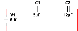
Figure: Circuit schematic of two series capacitors with DC voltage applied
First, find the CT.
(5 x 12 ) / (5 + 12 )= 3.529 µF
Calculate the CT / Cx
3.529 µF / 5 µF=0.7058
Multiply by the VS
.7058 x 3 V= 2.18 V
Capacitors in Parallel
The following figure shows three capacitors connected in parallel
By applying Kirchhoff’s current law, we obtain
${{i}_{T}}={{i}_{1}}+{{i}_{2}}+{{i}_{3}}\text{ }\cdots \text{ (10)}$
As we know that;
${{i}_{C}}=C\frac{d{{V}_{c}}}{dt}$
Using the fact that VT is the voltage across the parallel capacitors, we may rewrite eq. (10) as;
${{C}_{T}}\frac{d{{V}_{t}}}{dt}={{C}_{1}}\frac{d{{V}_{T}}}{dt}+{{C}_{2}}\frac{d{{V}_{T}}}{dt}+{{C}_{3}}\frac{d{{V}_{T}}}{dt}\text{ }\cdots \text{ (11)}$
Equation 11, can be written as
${{C}_{T}}={{C}_{1}}+{{C}_{2}}+{{C}_{3}}\text{ }\cdots \text{ (12)}$
In other words, eq. (12) states that when capacitors are connected in series, the total capacitance is equal to the sum of individual capacitors. Unlike parallel resistors and parallel inductors, which are added only by their reciprocals, parallel capacitors are combined like series resistors or series inductors.
Capacitors in Parallel Example
- Two capacitors valued at 24 µF and 30 µF are connected in parallel. What is the total capacitance?
Add the capacitance together.
24 µF + 30 µF= 54 µF
2. If a .4 µF, .2 µF, .68 µF, .99 µF, and a 6 µF capacitor are placed in parallel, what will be the total capacitance?
Add the capacitors together.
.4 µF + .2 µF + .68 µF + .99 µF + 6 µF= 8.27 µF
Since each branch of the parallel circuit gets the same voltage, the voltages across capacitors in parallel are the same as the voltage source.
- You May Also Read: Resistors in Series and Parallel
3 thoughts on “Capacitors in Series and Capacitors in Parallel”