The purpose of a battery charger is to charge a battery without overcharging it. The simplest type of charge controller for renewable energy systems monitors the battery voltage and turns the charging current off or reduces it when the battery voltage exceeds a specified level.
It turns the charging current back on when the battery voltage falls below another specified level; the charge controller turns the circuit on (closed) to resume the charging.
Trickle Charger Working
The simplest type of battery charger is the continuous trickle charger, which charges the battery at its self-discharge rate by applying a constant voltage and current, regardless of whether the battery is fully charged.
Because a simple trickle charger must be turned off manually after a period of time to prevent overcharging the battery, it is not generally used in renewable energy systems, although it could be used in a small home system.
The charging current can be preset to the trickle charge requirement for the particular type of battery, which is usually some percentage of the battery’s rating.
A portion of the total current from the source is diverted through the shunt control, and the rest of the current trickle charges the battery.
The current through the shunt control is set at a value that establishes the desired charging current to the battery. This charger provides the same current to the battery regardless of the charge state of the battery. This causes the battery to overcharge and potentially damages the battery once it is fully charged.
The circuit diagram in Figure 1 illustrates one possible configuration of a continuous trickle charger.
In this configuration, the source output voltage must be compatible with the battery voltage; if is not, a regulator must be used in series with the source to regulate the module voltage down to a battery-compatible level.
The diode prevents the battery from discharging back through the source should the module output drop below the battery voltage.
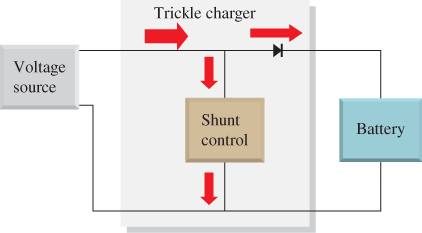
Figure 1 Continuous Trickle Charger Circuit Diagram
Float Charger Working
The float charger provides a relatively constant voltage, called the float voltage, that is applied continuously to a battery to maintain a fully charged condition.
-
On/Off Switched Float Charger
In its simplest form, the float charger is a trickle charger with an automatic on/off switch (usually a thyristor or a transistor). This charger senses when the battery voltage reaches a preset reference level (VREF1), which corresponds to full charge or float charge and shuts off the current to the battery.
When the battery discharges down to a second preset level (VREF2), it turns the current to the battery back on.
The sense resistor, R, is used to isolate the battery voltage from the output of the switch so that it can fluctuate independently of the source voltage.
The voltage sensing circuit compares the battery voltage to each of the two reference voltages and turns the shunt switch on or off accordingly. This setup overcomes the problem with the continuous trickle charge of having to turn it off manually.
It is not an ideal way to charge a battery, but it is better than continuous trickle charging that can overcharge the battery. The circuit diagram in Figure 2 illustrates one possible configuration of a float charger.
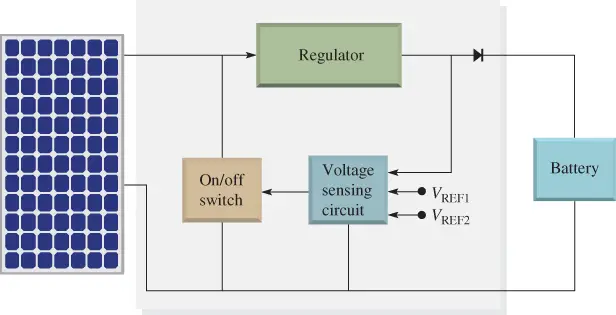
Figure 2 Switched Shunt Float Charger Circuit Diagram
In another type of float charger, the electronic on/off switch is in series with the source and load.
A regulator is used to set the current and voltage. Figure 3 shows the concept of a series float charger.
The graph in Figure 4 illustrates the idea of the series switched float charging. The noncharging portions of the time scale are compressed in order to show more than one on/off cycle.
The time during which the battery is not charging (discharge) is typically long compared to the time the battery is charging.
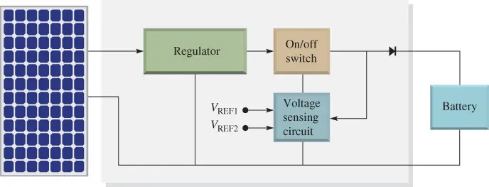
Figure 3 Switched Series Float Charger Circuit Diagram

Figure 4 Typical Series Switched Float Charging Curve
Three-Stage Float Charger
A characteristic of lead-acid batteries is that you charge them by applying a constant voltage and let the battery draw whatever amount of current it requires until it is fully charged.
A good way to charge a lead-acid battery is in three charging stages. These stages are
(1) Bulk stage (or constant current),
(2) Absorption stage (or topping or acceptance), and
(3) Float stage.
Figure 5 shows the charging stages for a typical battery.
- Bulk Stage
The stage of battery charging where the battery voltage increases at a constant rate is the bulk stage.
When a three-stage charger is applied to a battery that is significantly discharged, there is a maximum charge current to the battery.
The charger is set to the maximum battery voltage, which is typically 14.4 V to 14.6 V for a lead-acid battery at 25° C.
The battery voltage starts from the discharged level (VDISCH) and increases to VMAX at a nearly constant rate during this bulk stage, as shown in Figure 5.
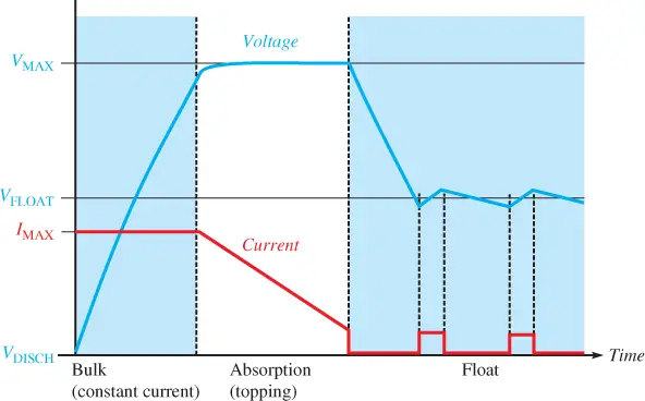
Figure 5 Charging Curves for a Three-Stage Charger with Switched Float
- Absorption Stage
The stage of battery charging after the battery voltage reaches the maximum and the current through the battery begins to decrease is the absorption stage.
When the battery voltage is 75% to 80% full, the current through the battery begins to decrease, marking the beginning of the absorption stage.
During this stage, the voltage is held at the maximum value while the current decreases. The decrease in current is not limited by the charger but by how much the battery can absorb; getting the correct rate for absorption is important for the longest battery life.
This absorption stage continues until the current through the battery decreases to a few percents of IMAX. At this point, the battery is fully charged and the battery current is much smaller.
- Float Stage
After the current to the battery reaches some lower level, the charger enters the float stage.
The float stage is the final maintenance or trickles charge stage with the purpose of offsetting any self-discharging of the battery. Typically, the float voltage is from 13.2 V to 13.8 V at 25° C.
During the float stage, the float current can be pulsed to keep the battery fully charged. During all three stages, the charger controls the voltage and supplies the current that is required to optimize battery life.
The circuit diagram in Figure 6 illustrates this process for charging the battery. The minimum current sensor issues a signal to the feedback control when the battery becomes fully charged. The feedback control then causes the regulator to decrease its output voltage to the float level.
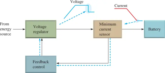
Figure 6 Function of a Three-Stage Charger
Review Questions
- What is a disadvantage of a trickle charger compared to a float charger?
- What does float charging mean?
- What are the stages of a three-stage charge controller?
- What happens during the bulk stage?
- What happens during the absorption stage?
Answers:
- The trickle charger must be turned off manually when the battery is charged or it may overcharge it.
- It is charging a battery in a manner that keeps it at its fully charged condition.
- Bulk, absorption, and float
- During the bulk stage, the battery is charged at its maximum rate.
- During the absorption stage, the battery continues to charge but at a rate determined by battery capacity.