Learn about the various components of a motherboard and their functions which play a crucial role in the functioning and connectivity of a computer system.
The motherboard is the main system board for the computer and connects all of the internal hardware components. This lesson will take a look at various components which are built into the motherboard. This lesson will also look at the expansion slots used to add hardware components to a system. The lesson finishes up with a discussion of the BIOS.
Lesson Objectives
By the end of this lesson, you will be able to:
- Identify the components on a motherboard.
- Identify the function of the Northbridge.
- Identify the function of the Southbridge.
- Recommend a motherboard for a given scenario.
- Identify appropriate BIOS settings.
- Differentiate expansion slots on the motherboard.
Instruction
A computer technician must have a strong understanding of the components used within a computer system. Understanding the purpose of each component provides the foundation of knowledge required to understand the operation of a computer system.
Motherboard Components and Functions
The motherboard is the largest printed circuit board, and every electronic device has one including computers, cell phones, printers, cars, and even toasters.
The motherboard determines the capabilities and limitations of a computer system. Every component on a computer system plugs into the motherboard is controlled by it and depends on it to communicate. The motherboard houses the following components:
- Central Processing Unit (CPU) – performs all basic arithmetic, logical, control, and input/output operations
- Chipset – manages the data flow between the computer’s processor, its memory and any peripheral devices attached
- Buses – a pathway that transfers data between components within a computer
- Random Access Memory (RAM) – a temporary form of computer data storage that allows fast access to data. RAM is volatile and requires power to keep data accessible.
- Expansion slots – provide expansion capability to add hardware components beyond what was originally installed
- Ports – provides an interface between the computer and a peripheral device such as a mouse, keyboard, or printer
All of the above components are labeled in Figure 1.
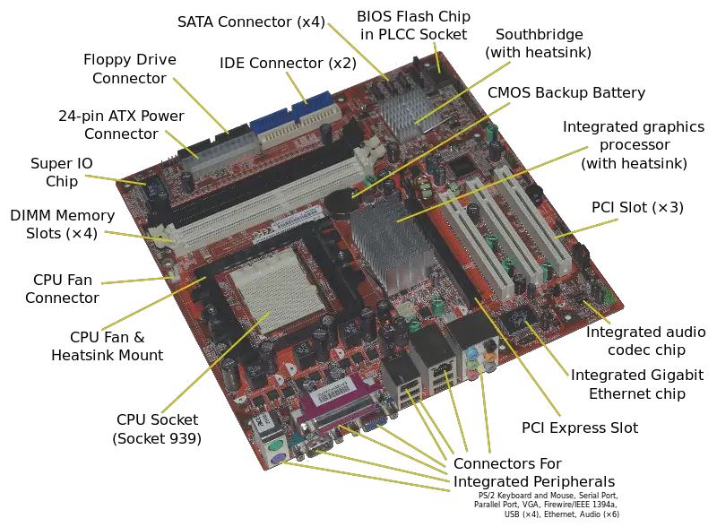
Figure 1: Motherboard Diagram with all components labeled
There are several components that comprise a motherboard. In this lesson, the following main components will be highlighted:
- System Clock
- Chipset
- Expansion Cards and Slots
- Front Panel Connectors
- Basic Input/Output System (BIOS)
- Complementary metal–oxide–semiconductor(CMOS)
- System bus with expansion slots
- Bus Structures
System Clock
Think of the system clock as the heartbeat of the motherboard. It sets the speed of all other components like the processor, memory, and buses. It has a base speed that is measured in hertz (Hz), but computers run in megahertz (MHz) or gigahertz (GHz).
Chipset
The chipset determines how system hardware and buses interact with the CPU and other components. It also determines how much memory can be added to a motherboard and what type of connectors the motherboard will have.
Current chipsets are made up of two distinct components – the Northbridge (NB) and Southbridge (SB).
The Northbridge controls RAM, the processor, and the Accelerated Graphics Port (AGP) video slot. It also regulates the speed the CPU can communicate with the components.
The Southbridge controls everything else connected to the computer including communication between the CPU and the expansion ports (hard drives, sound card, Universal Serial Bus (USB) ports, and other I/O ports).
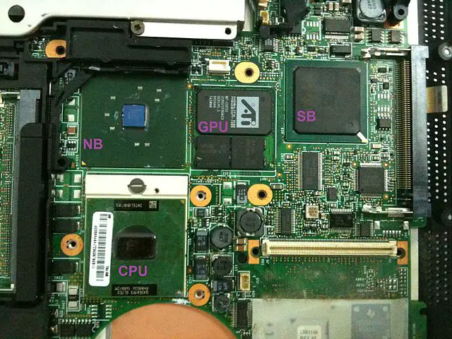
Figure 2: Components of a chipset
The Northbridge (labeled NB) and Southbridge (labeled SB) are both shown on a laptop motherboard in Figure 2.
Expansion Slots
Expansion slots allow the installation of extra components. Peripheral Component Interconnect (PCI), are used to install network cards, sound cards or modems.
AGP slots accommodate video cards with additional capabilities and PCI express (PCIe) cards to connect host bus adapters (HBAs) for expanded storage and cards for additional USB and Firewire ports.
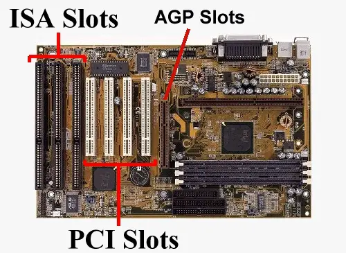
Figure 3: Expansion slots on a motherboard
Riser Cards
A riser card physically extends a slot so multiple cards can be plugged into a motherboard. The expansion cards will actually be turned 90 degrees to the motherboard. This allows cards to fit into a smaller space. Riser cards are usually only used in low-profile or slimline cases.
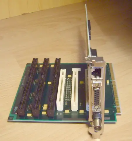
Figure 4: Multiple slot riser
The one slot on the motherboard can now accommodate multiple expansion cards.
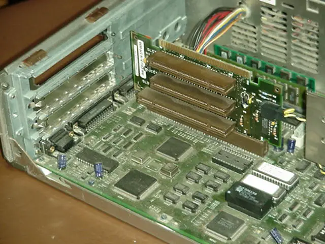
Figure 5: Multiple slot riser seated in a motherboard
Other Slots
Other slots encountered on the motherboard include the audio/modem riser (AMR) and the communications and networking riser (CNR). These two slots do basically the same thing with the CNR having a few additional functions. They were created to hold modems, network cards, and sound cards. You will seldom see these used on today’s motherboards.
As shown in Figure 6, the 30-pin AMR slot is much smaller than a PCI expansion slot. The 30-pin interfaces accommodate two formats making various audio/modem and audio network combinations possible.
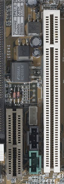
Figure 6: Audio/Modem Riser (AMR) slot next to white PCI slot
The AMR evolved into the CNR adding LAN and home networking functions.
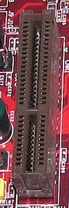
Figure 7: Communications and networking riser (CNR) slot
Front Panel Connectors
Front panel connectors are used to connect the power LED (light emitting diode) light on the front of the case to a hard drive, a small internal speaker for testing, the power button, and the reset button. There may also be additional LED lights for USB, Firewire and audio devices.
All of the front panel connectors from the case get plugged into tiny pins on the motherboard. The layout of the pins varies from motherboard to motherboard, although they are usually grouped together and color-coded. You may or may not use all of the connectors.
Sometimes the power LED has a blank pin between the two wires. You can buy an adapter to change the pin layout or simply cut the connector to accommodate the pins.
It is important to note that the reset jumper must be attached to the pins, in the correct order, before the computer will start. If nothing happens when you turn on the computer for the first time, check that the reset jumper was attached correctly.
You may view a visual installation of connectors to the pins on a motherboard at the following URLs:
It is important to remember that each motherboard is different, and it is important to look up the proper connections in the motherboard manual.
Figure 8: Connection schematic using a sample motherboard front panel connector
BIOS – Basic Input/ Output System
The Basic Input/ Output System (BIOS) may be referred to as the System BIOS or ROM (Read Only Memory) BIOS. The BIOS holds the motherboard’s firmware which is nothing more than a set of instructions. It is the first software run when the computer is powered on.
The fundamental purpose of the BIOS is to initialize and test the system’s hardware components and to load the operating system. The BIOS provides a consistent way for applications and the operating system to interact with I/O devices like the keyboard, mouse, display, and other connected devices.
BIOS and CMOS
Working with the BIOS is a chip known as the complementary metal–oxide semiconductor (CMOS). The CMOS holds the settings you selected in the BIOS. CMOS is volatile in nature. That means it must be supplied with continuous power that is supplied by a battery. If the battery runs down settings will be lost.
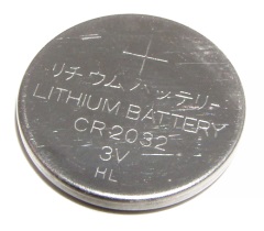
Figure 9: CMOS Battery
The BIOS has a menu-based user interface to make changes such as:
- Configure hardware
- Make changes to I/O ports
- Set the system time
- Enable or disable system components
- Set voltages for the CPU and memory
- Set the boot sequence
- Control fan speeds
- Set a BIOS and system password
- Enable or disable virtualization support
Users can set various password prompts, such as a password for securing access to the BIOS user interface functions itself and preventing malicious users from booting the system from unauthorized peripheral devices.
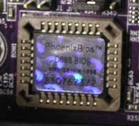
Figure 10: Phoenix BIOS chip
BIOS Options
The first thing the computer does when it is turned on is to run a diagnostic program called the Power on Self-Test or POST. The POST checks that all the motherboard components are functioning and can communicate with each other.
The BIOS can be accessed at system startup with a particular key sequence. This is usually the delete key or the F2 key, but different manufacturers may have a different sequence to press.
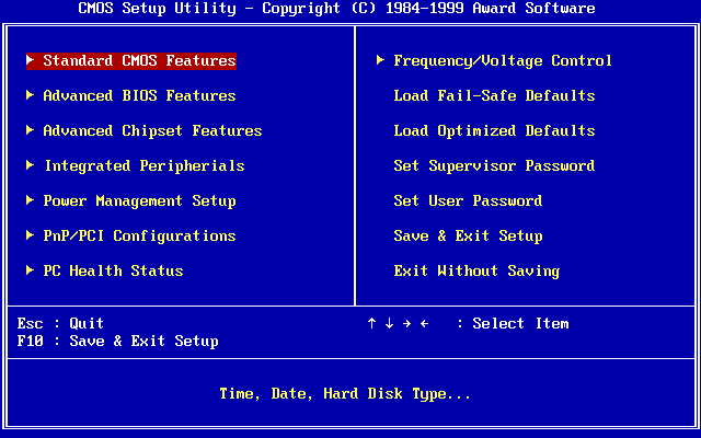
Figure 11: CMOS Setup Utility
Built-in tools can monitor the following:
-
- Temperature
- Fan Speeds
- Intrusion detection
- Voltages
- Clock
- Bus speeds
To see additional screenshots of various options that can be viewed and/or changed in the BIOS setup, browse to MSI 790GX-G65 Motherboard Reviews and scroll down to the bottom of the page.
The BIOS software is stored on a non-volatile ROM chip on the motherboard. This means the chip does not lose its contents even if there is no power going to the BIOS.
Using the BIOS menu, you are able to change hardware configurations such as the order in which the PC boots – floppy drive, hard drive, CD-ROM, USB.
The ROM BIOS is commonly called the computer’s firmware. Firmware used to be hardcoded on the chip and could not be changed without replacing the chip. Most modern devices can be upgraded when new features are added. This process is called flashing the BIOS.
Newer BIOS chips are made of Electrically Erasable Programmable Read Only Memory (EEPROM) chips. This type of chip allows the content of the BIOS to be rewritten without removing the chip from the motherboard. This way the BIOS software can be easily upgraded to add new features or fix bugs.
So what happens if you set a BIOS password and then forget what it was? The BIOS and system passwords can be easily erased along with all the other user settings. This can be done by removing the battery, waiting a few seconds and then putting it back in.
The most common way is to locate the CMOS reset jumper. Simply move the jumper to the enabled position (jumper on pins 2 and 3), and turn on the computer which sends an electrical signal to erase the CMOS. Be sure to then move the jumper back to the disabled or default position (jumper on pins 1 and 2). The CMOS is now back to the factory default settings.
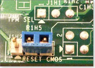
Figure 12: CMOS Reset jumpers
EFI and UEFI
Starting in 2011, the BIOS was replaced on some motherboards with a more complex Extensible Firmware Interface (EFI) or the Unified Extensible Firmware Interface (UEFI). This new BIOS type was introduced to provide more diagnostic and repair tools to the computer and provide a more efficient interface between the operating system and the components.
Initially made for the Itanium architecture, it is now available for x86 and x64 platforms and provides legacy support for BIOS services. It can support remote diagnostics and repair of computers, even without an operating system
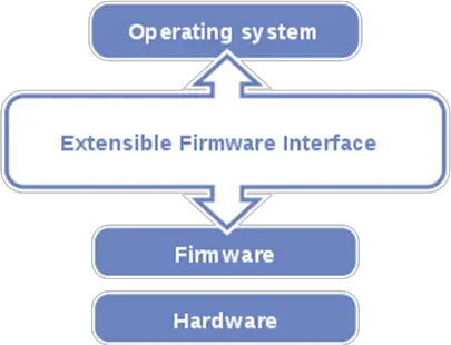
Figure 13: Extensible Firmware Interface (EFI)
Documentation
It is very important to document the settings you have changed in the CMOS. This way if something ever happens, like the CMOS battery runs down, you have a record of what the previous settings were and how to reset them.
It is recommended that you tape your documentation inside the case so anyone that works on that computer has a copy of your configuration.
Keep well-labeled, written record of:
- All changes you make to CMOS
- Records of hardware and software installed
- Network settings
Keep documentation up to date and in a safe place. Also, the document before you flash or replace the BIOS chip.
Bus Structures
A bus can be defined as a channel or path between components. The speed of the bus has a lot to do with the speed of the computer.
There are a lot of incredibly complex components in a computer, and all of these parts need to communicate with each other in a fast and efficient manner. Otherwise, the amazing speed and capabilities of each individual component is lost in the whole.
Typical Bus Structures
There are two key buses in a computer: the system bus and the shared bus.
The system bus is also called the local bus or front side bus. This bus connects the CPU to the system memory. It is one of the most important buses in the system. The faster the processors can move information in and out of the memory, the faster computers operate. When selecting a motherboard, find one with the fastest system bus possible.
The shared bus is what connects all the other components to our computer and moves information around inside the motherboard.
The shared bus connects the Industry Standard Architecture (ISA), Extended Industry Standard Architecture (EISA), PCI, and PCIe, USB, and Firewire buses together. This is done through bridges, which are part of the computer’s chipset. This bridge acts as a traffic cop, integrating the data from the other buses into the system bus. This bridge lets multiple devices access the same path to the CPU and system memory.
Most chipsets have two bridges: the Northbridge and the Southbridge. You can see in Figure 13 that the Northbridge controls the CPU, memory, and the AGP slot for video. The front side bus, memory bus, and AGP bus all connect to the Northbridge.
The Southbridge basically controls everything else. Hard drives, CD players, DVD players, PCI bus, and I/O ports are all connected to the Southbridge. The Southbridge regulates what bus and how much information can be passed to the Northbridge.
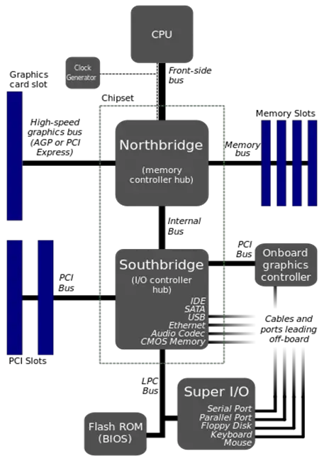
Figure 14: Bus structure
Key Takeaways of Motherboard
The motherboard is considered the nervous system of a computer. Everything that is not built into the motherboard is connected to it in slots or through ports. Its main components are the system clock, CPU, chipset, RAM, ROM BIOS, CMOS, power supply, ports, and the system bus with expansion slots.
Information stored in the BIOS is powered by the CMOS battery. Without the battery, the BIOS settings would have to be reset each time the host is booted. Information, such as the type of hard drive, the boot order, date and time, is stored in BIOS and is used by the host when it is booting.
Motherboard Components FAQs
What is a motherboard and what does it do?
A motherboard is the main circuit board of a computer that connects and allows communication between various hardware components, such as the CPU, RAM, and peripherals.
What are the common components found on a motherboard?
Common components found on a motherboard include the CPU socket, RAM slots, expansion slots, chipset, BIOS, connectors for storage devices, USB ports, and audio/video interfaces.
How do I choose the right motherboard for my computer?
When choosing a motherboard, consider factors such as the compatibility with your CPU and other components, the number and type of expansion slots, the available ports and connectors, and any specific features or requirements for your intended use.
Can I upgrade the components on my motherboard?
Yes, you can typically upgrade components on a motherboard, such as adding more RAM, upgrading the CPU, or installing additional expansion cards. However, compatibility with existing components and the motherboard’s specifications should be considered.
What is the importance of BIOS on a motherboard?
The Basic Input/Output System (BIOS) is firmware embedded on the motherboard that initializes the hardware and provides a software interface for configuration and control. It plays a critical role in the startup process and system settings of a computer.
Are motherboards interchangeable between different computer models or brands?
Motherboards are not interchangeable between different computer models or brands due to variations in form factors, component compatibility, and proprietary designs. It is important to choose a motherboard that is specifically designed for your computer’s model or intended use.
How do I troubleshoot motherboard-related issues?
When troubleshooting motherboard issues, ensure that all connections are secure, check for any physical damage or visible issues, update the BIOS firmware, test components individually, and consult technical support or documentation for further assistance.