The Open System Interconnection (OSI) reference model is an industry-standard framework created and maintained by the International Standardization Organization (ISO). The OSI model was created to make network devices and network protocols interoperable.
It allows components, such as hard drives and video cards, to function in a computer or network independent of the manufacturers. In networking, the OSI model defines how media, protocols, and standards work together.
The OSI model breaks the network process into seven manageable layers. It is used as a universal method for communicating network concepts and interpreting network functionality.
Each OSI layer performs a distinct set of functions. Following the OSI model when designing, building, upgrading, and troubleshooting will ensure greater compatibility and interoperability between network technologies and vendors.
The OSI model also makes possible an organized methodical approach to network troubleshooting.
Benefits of the OSI Model
Benefits of the OSI model include:
- Divides the aspects of network operations into less complex components.
- Standardizes interfaces, enabling engineers to specialize design and development efforts to specific functions.
- Facilitates modular engineering and prevents changes in one area from affecting others.
- Ensures interoperability and allows network designers to choose the right networking devices.
- Accelerates evolution and helps with testing and troubleshooting the network.
The first bullet refers to the fact that the OSI model divides networking concepts into seven hierarchical categories, the OSI layers. Figure 1 illustrates the seven layers of the OSI model, which we explore next.
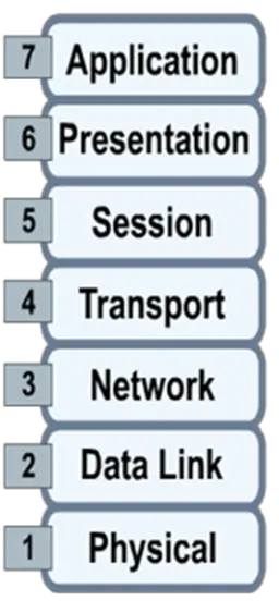
Figure 1: Seven Layers of the OSI Model
Seven Layers of the OSI Model
The seven layers of the OSI model begin with layer 1 at the bottom. Each layer only communicates with its neighbor layers. All traffic must enter and exit through layer 1.
It is important to learn the seven layers in order. Use the mnemonic device, “Please Do Not Throw Sausage Pizza Away” to help remember the seven layers of the OSI model.
The video, TCP/IP and the OSI Model Explained! (36:34), explains how the OSI Model maps to the TCP/IP protocol, review the function of each layer and discusses how the various network devices are mapped to the TCP/IP protocol.
Physical Layer – Layer 1
OSI layer 1 is the physical layer, illustrated in Figure 2. Two important words to associate with the physical layer are bits and media.
The physical layer is responsible for converting bits from a computer, represented by zeros and ones, into a signal that can be sent over the network. Signals are propagated over some media: twisted-pair cable, fiber optic cable, coaxial cable, or air.
The physical layer provides the electrical, mechanical, procedural, and functional means for implementing physical media for the purposes of propagating data via signaling.
Common layer 1 devices include repeaters and hubs. These are considered “dumb” devices because they do not make any decisions about what they are receiving or sending.
Cable installers primarily work at the physical layer. A large percentage of network problems occur at this layer and should be the first step when troubleshooting the network.
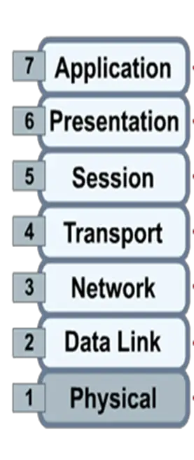
Figure 2: Layer 1 of the OSI Model
Data Link Layer – Layer 2
OSI layer 2 is the data link layer, depicted in Figure 3. The data link layer is responsible for supporting all network protocols that need to propagate over the physical media.
Layer 2 is also responsible for the speed of transmission, flow control, and error correction. The data link layer uses the physical topology to identify the devices and the media comprising the network. The data link layer is serviced by the physical layer.
The primary layer 2 networking devices are bridges and switches; these devices have some “intelligence” in that they make decisions about forwarding protocol data units (PDUs).
Bridges are legacy devices, meaning that they are rarely used in modern networks. Switches have replaced bridges because switches are faster, have more ports, and support more technologies.
The data link layer can be divided into two sublayers:
- Logic link control (LLC) – responsible for frame synchronization, flow control, and error checking along with identifying protocols like Ethernet or 802.3.
- Media access control (MAC) – the interface between the LLC and the physical layer, responsible for delimiting layer 2 PDUs, or frames.
Addressing frames is an important characteristic of a Layer 2 protocol. The address associated with a frame is called the physical address.
Ethernet is one type of layer 2 protocol. Ethernet defines a 48-bit physical address, called a MAC address, to identify a network interface on a computer or network device.
MAC addresses are hexadecimal addresses represented in various formats, depending on the operating system of the host device.
The first 24 bits of a MAC address identifies the make and model number of the network interface, and the last 24 bits uniquely identify the network interface on the Internet.
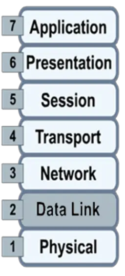
Figure 3: Layer 2 of the OSI Model
Network Layer – Layer 3
OSI layer 3 is the network layer. This is where most of the action takes place in the day-to-day work of networking professionals. The Internet exists largely because of the Internet Protocol (IP), a layer 3 protocol.
Historically, many layer 3 protocols were used for network implementations; but over time IP became the exclusive network layer protocol, so we often make the immediate association of IP with layer 3.
There are two fundamental implementations of IP: IP version 4 and IP version 6, with IPv6 slowly but surely replacing IPv4. The term packet, or datagram, is often used when referring to network layer PDUs, like IP packets.
The network layer is responsible for end-to-end path determination. Layer 3 network design ensures that every IP address is unique. IPv4 addresses and IPv6 addresses are two examples of network addresses or logical addresses.
A network has both a physical and a logical topology; the logical topology is associated with the network layer, and layer 3 addressing provides the hierarchical labeling scheme for the logical topology.
A subnet is a network that combines with other networks to form a larger network.
The networking device most often associated with layer 3 is a router. Routers interconnect to form the skeleton of the Internet. Routers define the networks that comprise the Internet. Routers forward IP packets through the Internet.
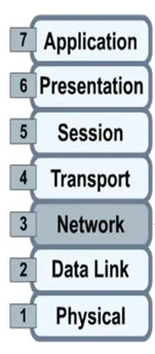
Figure 4: Layer 3 of the OSI Model
Transport Layer – Layer 4
OSI layer 4 is the transport layer, depicted in Figure 5. The transport layer is responsible for segmenting application data, regulating the flow of information, and enhance the quality of service (QoS) minimally provided by the network layer.
While the network layer is dedicated to moving data between remote networks, the transport layer instantiates and maintains the communication session specific to an application or service on the two hosts at each end of the session.
The term segment is often used to describe transport layer PDUs; for example, TCP segments and UDP segments are encapsulated by IP packets.
Historically, an array of layer 4 protocols was used in various types of networks. But the sieve of time resulted in the almost universal adoption of two primary transport layer protocols:
- Transport control protocol (TCP) – connection-oriented protocol with built-in reliability mechanisms that guarantee delivery of data between source and destination in virtual circuits, based on prescriptive operations: sliding windows and sequencing and acknowledgment of data segments.
- User datagram protocol (UDP) – a connectionless protocol that sends data without guaranteeing delivery or acknowledging its receipt. UDP is used with voice and video traffic, and other types of traffic where it is not as important to verify the arrival and order of data comprising a communication session. UDP is often the transport layer protocol of choice when speed is more important than reliability.
Layer 4 devices include firewalls. Firewalls not only make decisions about routing packets, but firewalls determine whether data satisfies the policies required to enter a network. The policy requirements are defined by both layer 3 and layer 4 parameters.
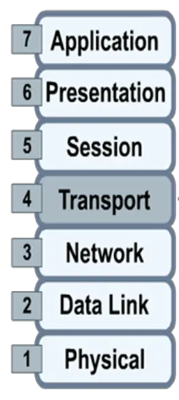
Figure 5: Layer 4 of the OSI Model
Session Layer – Layer 5
OSI layer 5 is the session layer, pictured in Figure 6. The session layer is responsible for establishing, maintaining, and terminating sessions between two computers. This includes starting, stopping, and re-synchronizing two computers as they communicate, a process called session control.
A keyword to remember for layer 5 is communication. The session’s characteristic of layer 5 are analogous to TCP virtual circuits, but involve more administrative overhead in order to provide greater functionality.
The data link layer services the network layer. The network layer services the transport layer. The transport layer services the session layer. The session layer services the presentation layer, which we explore next.
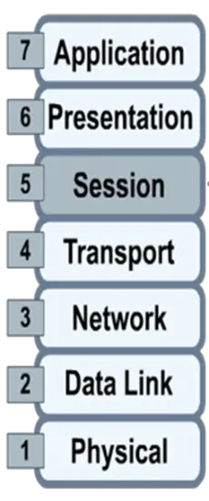
Figure 6: Layer 5 of the OSI Model
Presentation Layer – Layer 6
OSI layer 6 is the presentation layer, depicted in Figure 7. The presentation layer facilitates communication between applications on distinct computer systems in such a way that the mechanics of the facilitation are transparent to the applications. Layer 6 is responsible for three main functions:
- encryption/decryption
- compression/decompression
- the syntax which defines the communication, such as JPEG for graphics, TXT for text files, MP3 for audio files; all devices communicating must be able to speak the same language to interact.
The terms syntax and format are most often associated with the presentation layer. The presentation layer services the application layer.
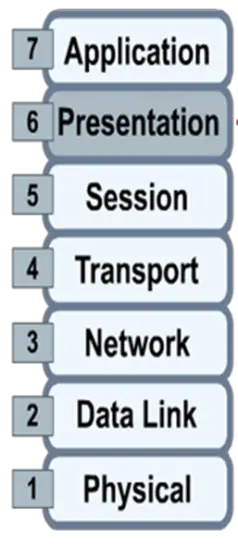
Figure 7: Layer 6 of the OSI Model
Application Layer – Layer 7
OSI layer 7 is the application layer, depicted in Figure 8. The application layer is the layer nearest to the user and provides services to applications used by the endpoint devices. It does not provide services to any other OSI layer.
The World Wide Web (WWW) is a system realized at the application layer of the OSI model.
The application layer is most often associated with services and applications such as Telnet, SSH, FTP, HTTP, HTTPS, and email (SMTP, POP, IMAP).
Word processing software and spreadsheet software are often bundled in an office software suite, and called office applications; modern office applications integrate with the application layer to facilitate sharing of office documents over the Internet as a means of real-time collaboration for project teams.
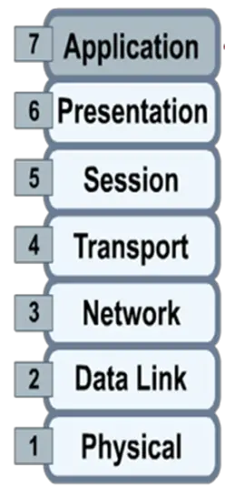
Figure 8: Layer 7 of the OSI Model
Encapsulation
Encapsulation is the process of placing one PDU inside another PDU for network delivery. See Figure 9.
As data moves down the OSI layers, PDUs are recursively encapsulated in PDUs associated with the respective layers. At each stage of encapsulation, headers and footers are prepended and appended to the respective PDU to create a new PDU.
The process can be described in five steps, using the PDU terminology we have adopted:
- Data – Data consists of strings of alphanumeric characters used by a computer system application.
- Segments – The data is packaged into segments for end-to-end transport. By using segments, the transport layer ensures that the message hosts at both ends of, say, an email system can reliably communicate.
- Packets – The segments are encapsulated within packets, or datagrams, that include network headers with source and destination logical addresses (usually IPv4 or IPv6).
- Frames – The frames traverse a one-hop singular path directly connecting one network device to another network device; the hop is one link of a chain of links comprising an end-to-end network communication instance. The frame header includes the source and destination physical addresses required for data link layer communication.
- Bits – The binary (electrical or optical) information sent over a medium as signals.
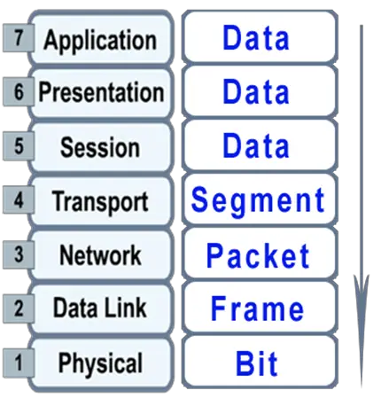
Figure 9: Encapsulation
Summary
In this lesson, the seven-layer OSI model was introduced. The benefits of using the OSI model were explained. Each layer was described in some detail.