This guide covers efficiency and losses of DC Machines (Motor and Generator) which include Copper, Core, Brush, Mechanical (Friction and Windage), and Stray losses.
Losses in DC machines (motor and generator) include friction, windage and electrical losses. Friction is present in all rotating machinery. Windage is present because of air resistance to rotating components, and in fans added to ensure forced circulation of air for cooling purposes.
In electrical machines the term ‘other losses’ comprises copper losses, iron losses, magnetic leakage and other lesser factors. Together the losses are wasted energy which should be reduced as much as possible, often by simple good maintenance.
Losses in DC Machines
Losses
Copper power losses are due to the resistance of electrical windings, while iron power losses are due to hysteresis and eddy currents in the iron core of the armature. While the iron loss is almost constant from no load to full load, the copper loss varies considerably due to load current.
These two are the main electrical losses in a motor and are added to obtain the total electric power loss. The power loss in copper conductors varies as the square of the current flowing (P = I2R).
At light loads, the small current flow means the copper loss is at a minimum. If the armature current is doubled, the copper loss becomes four times as great and four times as much heat is generated; this heat has to be removed, usually by air circulation, which adds a further loss to the system.
DC Generator Efficiency
For analysis purposes it is usual to assume that all the armature resistance is concentrated into one component and not distributed throughout the windings. Figure 1 shows a DC shunt-connected generator separated into its various imaginary component parts, while the broken lines indicate actual components.
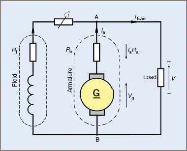
Figure 1 Equivalent circuit of a shunt generator
If the designed generated voltage of the generator in Figure 1 is 200 V, and the armature has a resistance of 0.5 Ω, then for every ampere of current being supplied by the armature there is an internal voltage drop of 0.5 V due to the armature resistance.
For every 2 A of load current, 1 V will be lost internally and if 200 V is required at the generator terminals then the generating section will have to generate a higher voltage in the windings. That is, for a 10 A load the generated voltage will have to be 205 V to give a terminal voltage of 200 V between points A and B.
The armature current Ia will also include the field current If as well as the load current Iload, that is:
![]()
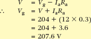
The voltage drop due to internal resistance is equal to IaRa (V = IR) and the generated voltage Vg is equal to the terminal voltage V plus the IaRa voltage drop. That is for a DC generator:
![]()
With a series field winding the resistance of the field must be added to the armature resistance.
DC Generator EMF Calculation Example 1
Find the value of the EMF generated in a DC generator if the terminal voltage is 204 V, the armature resistance is 0.3 Ω, and the armature current is 12 A.
DC Generator Terminal Voltage Calculation Example 2
Find the terminal voltage of a DC compound generator given the following facts:
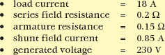
From the circuit shown in Figure 3:
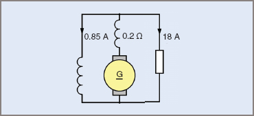
Figure 3 Circuit for Example 2
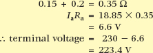
![]()
Total armature circuit resistance equals:
The overall efficiency of a DC generator can be found by adding all the losses to the output power and comparing this with the input power. Figure 2 shows the losses generally found in a machine. While appearing to be a considerable number, several are relatively small and an efficiency of 80 per cent or better is quite common.
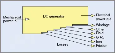
Figure 2 Losses in a DC generator
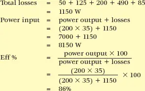
DC Generator Efficiency Calculation Example 3
Find the input power and efficiency of a DC generator supplying a load of 35 A at an output voltage of 200 V.
The losses are as follows: friction 250 W, iron 125 W, field 200 W, armature copper losses 490 W, other stray losses 85 W.
DC Motor Efficiency
The theoretical approach to the efficiency of a DC motor is similar to the DC generator method. Armature resistance is considered as one component and the winding as another. This is shown in Figure 4, and the similarity to Figure 1 can easily be seen.
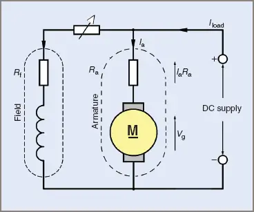
Figure 4 Equivalent circuit of a DC shunt motor
The back EMF generated is subject to the armature voltage drop (IaRa) and is equal to the difference between the supply voltage and the IaRa voltage drop. That is, for a DC motor:
![]()
The only variation from the formula for DC generators is the polarity of the armature voltage drop (IaRa). This is illustrated in Figure 4 with arrows indicating the directions of the applied and generated voltages, and showing them opposing each other. The result is that the effective voltage causing a current to flow through the armature circuit is smaller than the applied voltage. That is:
![]()
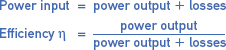
The overall efficiency of a DC motor can be found in a similar manner to that of a DC generator,
that is: power input = power output + losses.
Whereas the input to a generator was mechanical power and the output electrical power, the input to a motor is electrical power and the output mechanical power. The losses are shown in Figure 5.
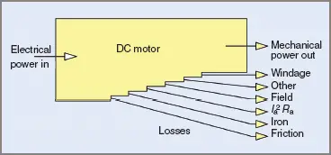
Figure 5 Losses in a DC motor
DC Motor Back EMF Calculation Example 4
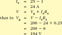
A shunt-connected DC motor draws 25 A on a 200 V DC supply. If the motor field has a current of 1 A and the armature resistance is 0.25 Ω, find the value of the back EMF. The circuit is shown in Figure 6.
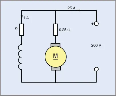
Figure 6 Circuit for Example 4
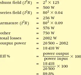
DC Motor Efficiency Calculation Example 5
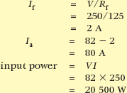
A 250 V DC long-shunt, compound motor takes a current of 82 A at full load.
Calculate the output power and the efficiency, given the following details:
- armature resistance = 0.09 Ω
- shunt field resistance = 125 Ω
- series field resistance = 0.04 Ω
- total of all other losses = 750 W
The circuit is shown in Figure 7.
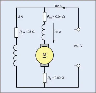
Figure 7 Circuit for Example 5
losses: