This article covers five types of losses in DC machines including Copper losses (I2R), Core Losses, Brush Losses, Mechanical Losses, and Stray losses.
The losses in a DC machine affect its cost, rating, and performance. The efficiency of a rotating machine is frequently determined by measuring the losses, using techniques that are precisely defined by ANSI, IEEE, and NEMA measurement standards.
The efficiency is defined the same way as it is for transformers and other types of machines:
\[\begin{matrix} \eta =\frac{Output\text{ }Power}{Input\text{ }Power}=\frac{Input-Losses}{Input}=\frac{Output}{Output+Losses} & {} & \left( 1 \right) \\\end{matrix}\]
Typical efficiencies of DC motors are shown in Table 1. Generators would have similar efficiencies except they would be rated in kW.
The types of losses in an electrical machine are basically the same regardless of the type of machine. The amount of loss in each category depends on the number of windings, type of core, whether the machine has brushes, etc.
Table 1: Typical Efficiencies for Various Size DC Motors
| Machine Size (HP) | Typical Efficiency (%) | Typical losses (HP) |
| 5 | 74 | 1.76 |
| 50 | 89 | 6.18 |
| 500 | 93 | 37.6 |
| 5000 | 97 | 155 |
Ratings and Heating of DC Machines
One of the most important factors in selecting a DC motor is its maximum continuous output power. Electrical machines are always rated in terms of the output they can provide.
The machine’s power rating depends primarily on its allowable operating temperature and how fast it can dissipate the heat that results from the losses in the machine.
The machine must meet performance standards, and its life must not be reduced by overheating when operating at its rated power. The DC machine rating is always the output of the machine (shaft horsepower for a DC motor and output kW for a DC generator). Figures 1 and 2 show the power flow through a DC generator and motor, respectively.
In each case, a power of one form is input to the machine and losses are subtracted one by one, until the output side.
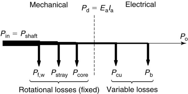
FIGURE 1: Power flow for a DC generator.
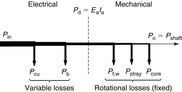
FIGURE 2: Power flow for a DC motor.
Types of Losses in DC Machines
The losses in the DC machine are similar to those of the transformer and other types of rotating machines. Like AC machines, DC machines have copper, steel, rotational, and stray losses. Unlike the induction motor, however, the DC machine also has losses in the brushes. Whether the machine operates as a motor or as a generator, the losses can be summed as
\[\begin{matrix} {{P}_{loss}}={{P}_{aw}}+{{P}_{ip}}+{{P}_{cw}}+{{P}_{fld}}+{{P}_{b}}+{{P}_{fw}}+{{P}_{fe}}+{{P}_{stray}} & {} & \left( 2 \right) \\\end{matrix}\]
The first four terms on the right-hand side of equation 2 are copper losses in the armature winding, the inter-poles, the compensating winding, and fields coils (either series, shunt, or both). The remaining terms are Pb, the loss due to the brushes; Pfw, the friction and windage loss; Pfe, the hysteresis and eddy current losses in the machine core; and Pstray, the stray losses.
Copper Losses in DC Machine
Copper losses are found in all the windings of the machine. By convention, they are computed using the DC resistance of the winding at 75°C. The actual resistance depends on the operating frequency and flux conditions. Any difference between the actual and computed copper loss is ac counted for under the stray-loss category.
Brush Losses in DC Machine
Two types of brushes are commonly used in DC machines, graphite (carbon) or metal- graphite. In either case, the brushes have resistance and will thus dissipate power. Generally, the brushes are assumed to have a constant voltage drop across them, 2.0 volts for graphite brushes and 0.5 volts for metal-graphite brushes.
Mechanical Losses in DC Machine
The mechanical or friction and windage losses are due to the friction in the bearings and the energy that is dissipated in turning the rotor through the air inside the machine.
The rotational losses can be determined by driving the machine at rated speed with no load or excitation. Rotational losses are frequently lumped with core loss and determined at the same time.
Open-Circuit or No-Load Core Losses in DC Machine
The core loss due to hysteresis and eddy currents is measured at no load, and the combination of the core losses with the mechanical losses constitutes the no-load rotational loss. It should be noted that distortion of the field, such as by armature reaction, may significantly increase the core loss. The difference between the measured and actual core loss is put in the stray-loss category.
Stray Losses in DC Machine
By convention, stray load losses are considered to be 1% of the rated output for DC machines.
Generator Power Flow
In the case of a generator, we apply mechanical power to the shaft of the machine and deliver electrical power to a load. As shown in Figure 1, mechanical power is input at the left side of the diagram.
Rotational losses are mechanical in nature and are thus subtracted from the mechanical power. This includes not only friction and windage but, by convention, stray losses and core losses. The remaining power is transformed into electrical power, and this quantity is called the developed power.
In the case of a DC generator, the developed power is
$\begin{matrix} {{P}_{d}}={{E}_{a}}{{I}_{a}} & {} & \left( 3 \right) \\\end{matrix}$
Thus, the power in the controlled voltage source of the equivalent circuit represents the developed power.
From the developed power we subtract the copper losses in the machine windings, as well as the loss due to the brushes.
Note that in a self-excited DC generator, the field losses would be included in the copper losses, whereas in a separately excited DC generator the field losses would constitute a separate electrical input that would also be added to the losses of the machine. The final result is the electrical output of the generator.
Motor Power Flow
Motors receive electrical power as their input and deliver mechanical power at the shaft of the machine. In this case, as shown in Figure 2, the electrical power is input at the left. The copper and brush losses are subtracted, leaving the developed power in the middle.
As with the generator, the developed power is represented in the equivalent circuit of the DC motor by the power in the controlled voltage source and is calculated from equation 3.
From the developed power, we subtract the friction and windage, core, and stray losses to find the output mechanical power.
Maximum efficiency
The rotational losses of the machine are basically fixed, assuming the speed of the machine is constant. Whenever the machine is running, they are present.
The copper and brush losses, however, are a function of the machine load and are proportionate to the current squared.
In general, the maximum efficiency of an electrical machine (or transformer) occurs when the variable (I2R) losses are equal to the fixed losses.