The magnetization curve produced when the machine is separately excited still applies in the case of self-excited DC generator. That is, a given value of field current will produce a specific value of the generated voltage at a given speed, regardless of how the field winding is connected. However, there are other constraints that must be satisfied. Figure 1 shows a self-excited, shunt DC generator, operating at no load.
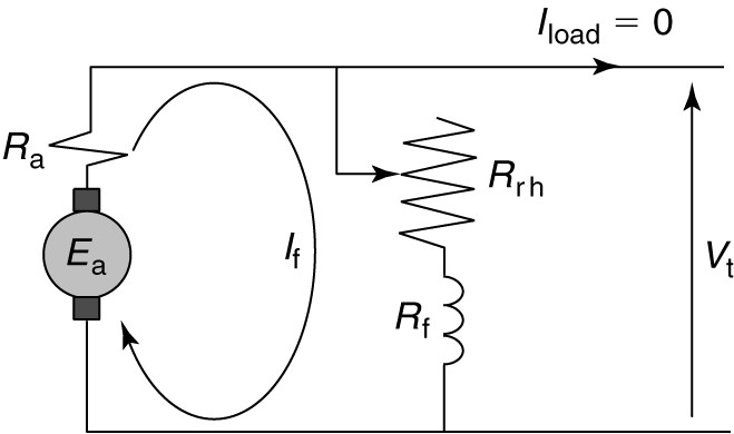
FIGURE 1: Self-excited, DC generator circuit.
Because the load current is zero, the only current in the armature winding is the field current. Writing a voltage loop through the armature and field circuits as shown results in the following relationship:
\[\begin{matrix} {{E}_{a}}\text{ }=\text{ }{{I}_{f}}({{R}_{a}}\text{ }+\text{ }{{R}_{rh}}\text{ }+\text{ }{{R}_{f}})\text{ } & {} & \left( 1 \right) \\\end{matrix}\]
Equation 1 is called the field circuit equation. It represents a linear volt-amp characteristic, which has a slope equal to the sum of the three resistances on the right-hand side of the equation. The constraints imposed by the magnetization curve and by equation 1 must be satisfied simultaneously. For both constraints to be satisfied:
The operating point of the generator must be at the intersection of the magnetization curve, with a straight line representing the field circuit equation, as shown in Figure 2.
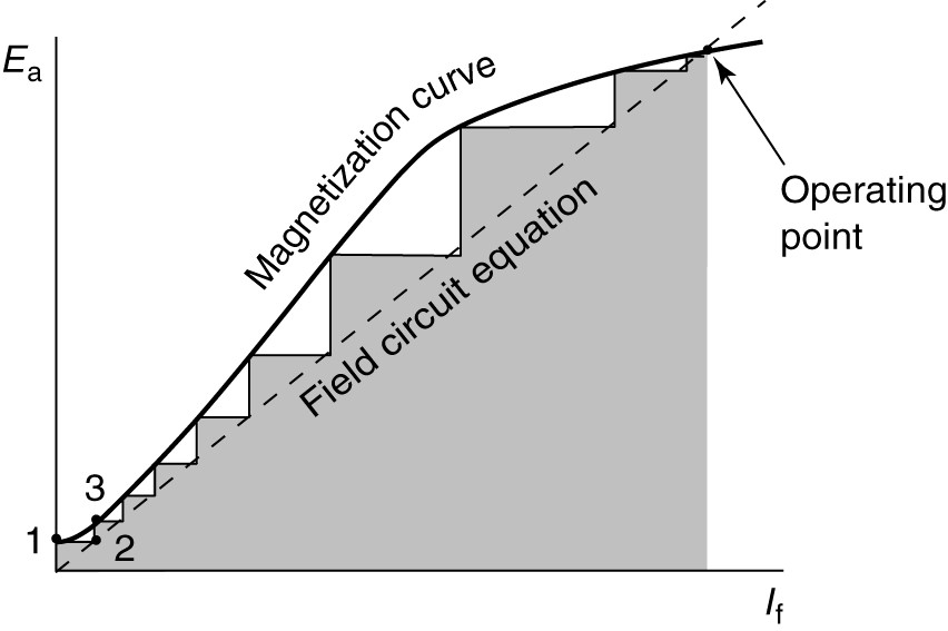
FIGURE 2: Determination of operating point of a self-excited DC generator.
The self-excited generator requires some residual magnetism in the field poles in order to generate the voltage.
Looking at Figure 2, when the generator is turned, the residual flux induces a small armature voltage (point 1). That voltage causes a field current (point 2) that, assuming the polarity is correct, increases the voltage more (point 3), which causes more field current and so forth. The dotted line in Figure 2 shows the process, which is called building up.
Significance of Saturation in Self-Excited DC Generator
Saturation makes the voltage buildup in the self-excited shunt DC generator feasible. Suppose the armature voltage was linear with the field current, as shown by the heavy solid line in Figure 3. The field circuit equation also is a straight line.
If the resistance of the field circuit is too low (as shown by the dotted line), then the two lines won’t intersect and there would be no steady-state operating point. The voltage would build up forever (or at least until the insulation broke down).
If the field circuit resistance is higher (as shown by the dot-dash line), then an operating point may occur, but it will change wildly with small changes in the field resistance because the slopes of the two intersecting lines are similar.
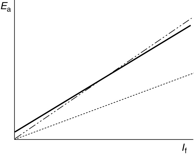
FIGURE 3: Illustration of the importance of saturation for voltage build-up in the self-excited DC generator.
Saturation also provides an upper limit to the amount of resistance in the field circuit.
Figure 4 shows what happens with different values of resistance in the field circuit. If the field resistance is too high, the voltage only builds up to a small value, as shown by the dot-dash line.
If the field resistance is such that the field circuit voltage requirement line runs close to the linear part of the magnetization curve, then the machine will not provide stable voltage, as shown by the dotted line in Figure 4.
Finally, if the resistance is of a suitable value, then the generator provides voltage, as shown by the dashed line.
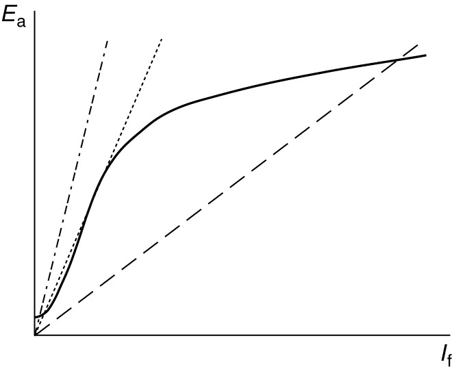
FIGURE 4: Effect of field circuit resistance on the generated voltage of a self-excited DC generator.
Variation of the Generated Voltage with Speed
Figure 5 shows the effect of varying the generator speed, n. Figure 5 (a) shows five magnetization curves, corresponding to five evenly spaced operating speeds. Also shown is the field circuit equation line, which intersects each of the magnetization curves.
When the speed changes, we move to a new magnetization curve while moving down the field circuit equation line. As a result, the voltage drops very quickly when the speed is reduced for a self-excited, shunt DC generator.
Recalling the voltage equation, decreasing the speed decreases the generated voltage, which in turn reduces the field current and flux, thus further reducing the generated voltage. Therefore, the voltage versus speed plot is nonlinear for the self-excited DC generator, as shown in Figure 5 (b).
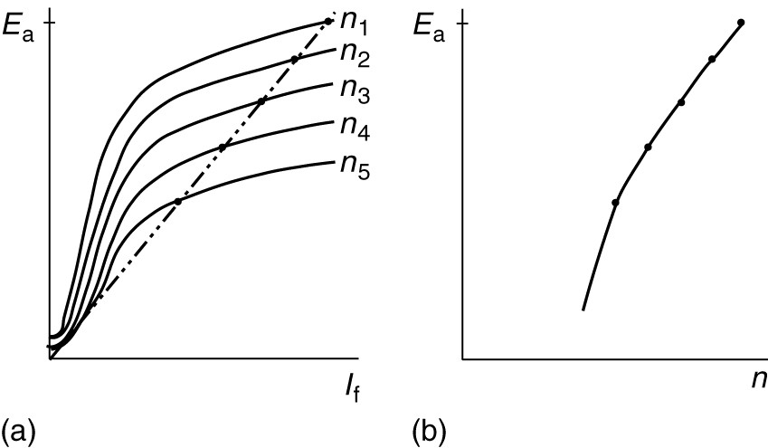
FIGURE 5: Performance of self-excited generator as the speed varies.
a. An intersection of field circuit line with generated-voltage curves at several speeds.
b. Resulting generated voltage as a function of speed.
Conditions for Voltage Buildup in Self-Excited DC Generator
Based on the discussion thus far, we can conclude there are several requirements for the voltage to build up in a separately excited DC generator. These requirements are:
- There must be residual magnetism in the machine pole pieces.
- The field coil must provide flux in the same direction as the residual flux. Otherwise, the machine will build down to zero volts.
- The field circuit resistance must not be excessive.
- The machine must have sufficient speed because the voltage is a function of speed.
Voltage under Load in Self-Excited DC Generator
By putting a variable load on the self-excited DC generator, we could observe the effect on the terminal voltage of varying the load current. Three effects would be observed, as shown in Figure 6:
- As the load increases, the load voltage declines due to the resistance of the armature. This is a linear effect, as shown by the dot-dash line in Figure 6.
- As the armature current increases, armature reaction reduces the flux per pole, further reducing the voltage, as shown by the dotted line in Figure 6.
- Reduction of the field voltage by these two factors causes the field current to decrease, lowering the voltage some more, as shown by the solid line in Figure 6.

FIGURE 6: Volt-amp characteristic of a self-excited DC generator.
As the load increases (meaning the load resistance decreases) the armature current increases. Based on the factors listed, the generated voltage would decline as the load increased. Eventually, however, the generated voltage decreases so much that the load current starts decreasing. The decrease in load current causes the volt-amp characteristic curve to turn around, as shown.
As the load resistance is decreased, the current and terminal voltage continues to decrease, until the short-circuit current is reached at zero-load voltage. This is an advantage for the separately excited generator because the short-circuit current can be less than the rated current of the machine. The point where the curve turns around is called the breakdown point, which usually occurs at about 150% of rated current.