The goal of this module is to provide learners with tools for understanding the operations of XNOR and XOR gates and enable learners to apply Boolean rules to find the Sum of Products (SOP) and the Product of Sums (POS).
Objectives
The learner will be able to:
- Explain the operation of XNOR and XOR gates
- Write the schematic symbols for XNOR and XOR gates
- Describe the development of Boolean laws
- Identify and apply DeMorgan’s Theorem for logic simplification
- Carry out the logic in Sum of Products (SOP) form
- Carry out the logic in the product of Sums (POS) form
Orienting Questions
- What are XNOR and XOR gates?
- What are the schematic symbols of XNOR and XOR gates?
- What is DeMorgan’s Theorem for logic simplification?
- How do you determine the Sum of Products (SOP)?
- How do you determine the Product of Sums (POS)?
Introduction
The purpose of this module is to continue the discussion of Boolean rules and laws with the addition of DeMorgan’s theorem and to explain the operation of XNOR and XOR gates.
XOR gates
The next gate we will investigate is the operation of the XOR gate. XOR gate operation is similar to a basic circuit as shown in Figure 1 below. The inputs are represented by the switches sw1, and sw2 and the output is represented by the lamp. The “state” of sw1 and sw2 determines whether or not the lamp illuminates. The condition for which the lamp is on is that sw1 or sw2 must be in opposite states. We can represent all possible states or conditions of sw1 and sw2 and the associated output through a truth table.
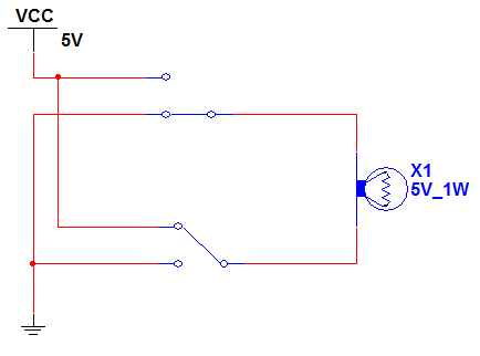
Figure 1: Basic Circuit
Therefore, a truth table for this setup would look like the following:
| SW1 | SW2 | Bulb |
| Open | Open | Off |
| Open | Closed | On |
| Closed | Open | On |
| Closed | Closed | Off |
This circuit configuration is the equivalent of the basic XOR gate. The XOR gate is then defined as a digital circuit whose output is “high” if both inputs are in opposite states”.
The schematic representation of an XOR gate in digital circuits is:
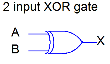
Figure 2: XOR Gate in Digital Circuits
A and B are the inputs to the gate, and X is the corresponding output.
The truth table for the 2 input OR gate in terms of Binary numbers is:
| A | B | X |
| 0 | 0 | 0 |
| 0 | 1 | 1 |
| 1 | 0 | 1 |
| 1 | 1 | 0 |
0 = “off” or “low”
1 = “on” or “high”
XNOR gates
The next gate we will investigate is the operation of the XNOR gate. XNOR gate operation is similar to a basic circuit as shown in Figure 3 below. The inputs are represented by the switches sw1, and sw2 and the output is represented by the lamp. The “state” of sw1 and sw2 determines whether or not the lamp illuminates. The condition for which the lamp is on is that sw1 or sw2, or sw1 and sw2 must be closed. We can represent all possible states or conditions of sw1 and sw2 and the associated output through a truth table.
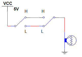
Figure 3. Basic Circuit
Therefore, a truth table for this setup would look like the following:
| SW1 | SW2 | Bulb |
| Open | Open | On |
| Open | Closed | Off |
| Closed | Open | Off |
| Closed | Closed | On |
This circuit configuration is the equivalent of the basic XNOR gate. The XNOR is then defined as a digital circuit whose output is “high” if both inputs are low, OR both inputs are high.
The schematic representation of an XNOR gate in digital circuits is:
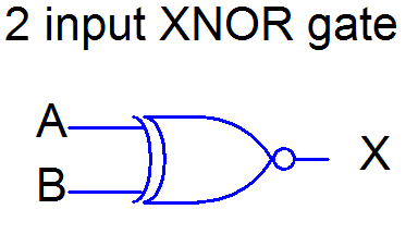
Figure 4: XNOR Gate in Digital Circuits
A and B are the inputs to the gate, and X is the corresponding output.
The truth table for the 2 input OR gate in terms of Binary numbers is:
| A | B | X |
| 0 | 0 | 1 |
| 0 | 1 | 0 |
| 1 | 0 | 0 |
| 1 | 1 | 1 |
0 = “off” or “low”
1 = “on” or “high”
Demorgan’s Theorem
In order to begin discussing logic simplification, we must address one final theorem known as DeMorgan’s Theorem. We will add these theorems to our other Boolean rules so that we can apply.
Theorem #1
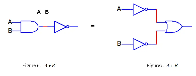
\[\overline{A\bullet B}=\overline{A}+\overline{B}\]
|
= |
|
The above states that A AND B NOT equals to A NOT OR B NOT
Theorem #2
\[\overline{A+B}=\overline{A}\bullet \overline{B}\]

|
= |
|
Note for both theorems, the truth tables are equal. We will show how to apply De-Morgan’s theorems in the next module on logic simplification.
Remember, the above states that A OR B NOT is equal to A NOT AND B NOT
Combinatorial Logic Standard Expressions
For any combinatorial logic configuration, the expressions can be reduced to express a Product of Sums (POS) or a Sum of products (SOP). In this section, we will learn about these type expressions and how to implement logic in Sum of Products (SOP) and Product of Sums (POS) forms.
SUM OF PRODUCTS (SOP)
Sum of products is a standard way of representing combinatorial logic circuits. It is made up of AND gates (product) followed by an OR gate (Sum) as shown in figure 10 below.
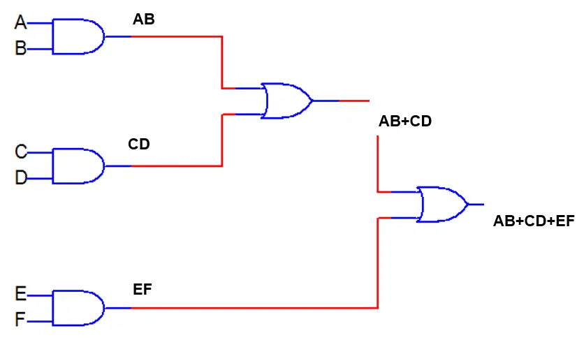
Figure10. Sum of products
We can convert a logic expression to the sum of products form simply by applying the appropriate laws outlined in chapter two, that is, the associative and distributive laws.
Sum of Product Example
Convert the following expressions to SOP form
1.
(A+B+C) (DE)
Solution,
ADE + BDE + CDE
2.
(A+B+D) (A +C)
Solution,
AA+AC+AB+BC+AD+CD
As you can see, we simply applied the distributive law and carried through each expression. We will practice more on these problems at the end of the module.
Now, notice the expressions above. Each product term does not contain all of the variables. For the final expression to be considered standard Sum of Products form, each of the terms in the SOP expression must contain all of the variables. Let’s look at a second example:
Convert the following expression to standard SOP expression
(AB) (C+D)
Solution,
ABC+ABD
Now, remember, to be a standard SOP expression, each of the product terms must contain each of the variables. Notice the first product term is missing D term and second product term is missing C term.
How do we tackle this? Well,
- Take each product term and multiply it by its missing variable plus its missing variable complement ($A+\overline{A}$ = 1) and carry through using distribution law.
- Keep doing this until each product term reflects all variables found in the whole expression.
- Add together all the new terms
Now, back to our solution,
ABC+ABD
Look at first term, it is missing D, so
ABC ($D+\overline{D}$ ) = ABCD + ABC$\overline{D}$
Look at the second term, it is missing C, so
\[ABD\text{ }(C+\overline{C})\text{ }=\text{ }ABCD\text{ }+\text{ }AB\overline{C}D\]
Now add the corrected first and second terms, the Standard SOP expression for
\[\left( AB \right)\text{ }\left( C+D \right)\text{ }=\text{ }ABCD\text{ }+\text{ }ABC\overline{D}+\text{ }ABCD\text{ }+\text{ }AB\overline{C}D\]
If each product term is missing more than one variable, perform the same operation for each missing variable until all variables are accounted for in each product term.
A Product Of Sums (POS)
A product of Sums (POS) is another standard way of representing combinatorial logic circuits, although not as common. It is made up of OR gates (sum) followed by an AND gate (product) as shown in figure 11 below.
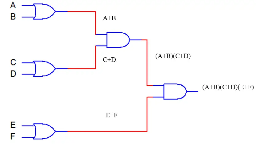
Figure 11. Product of Sums
Just as we wrote a standard sum of products (SOP) expressions, we can also write the standard product of sums expressions. Remember each term in the SOP expression contained all of the terms, and the product of sums expressions is no exception.
A product of Sum Example
Convert the following expression to standard POS expression
(A+ )(A+B)
Remember, to be a standard POS expression, each of the sum terms must contain each of the variables.
Notice the first sum term is missing B term and second sum term is missing C term.
How do we tackle this? Well,
- Take each individual sum term and add it to its missing variable “anded” with its missing variable complement (A ) and apply Boolean rule A+BC = (A+B)(A+C)
- Keep doing this until each sum term reflects all variables found in the whole expression.
- Add together all the new terms
Now, back to our problem,
(A+ )(A+B)
Look at the first term, it is missing B, so
A+C +B = (A+B+C)(A+ +C)
Look at the second term, it is missing C, so
A+B +C = (A+B+C)(A+B+ )
Now add the corrected first and second terms, the Standard SOP expression for
(A+ )(A+B)= (A+B+C)(A+ +C) (A+B+C)(A+B+ )
If each sum term is missing more than one variable, perform the same operation for each missing variable until all variables are accounted for in each sum term.