A schematic diagram is a drawing that shows electrical system circuitry with symbols that depict electrical devices and lines representing conductors.
Only qualified persons should review schematic diagrams and perform work on circuit breakers. A qualified person is a person who has special knowledge, training, and experience in the installation, programming, maintenance, and troubleshooting of electrical circuit breaker equipment and also has the safety skills and knowledge that allow him/her to perform the task safely.
Schematic diagrams are required for the setup and operation of common circuit breakers from OEMs such as ABB/ITE, General Electric, and Westinghouse/Cutler- Hammer.
Many Low-Voltage Circuit Breakers (LVCBs) and virtually all medium-voltage metal-clad circuit breakers use electrically operated mechanisms. Electrically operated circuit breakers have trip and close circuits, a spring-charging motor, and indicator lights. Understanding how these control circuits function is important when troubleshooting circuit breakers. It is standard protocol to show the control circuits for a circuit breaker in a schematic diagram in a de-energized condition just as it would be sitting in a cubicle with no control power applied.
Interpreting Common Circuit Breaker Schematic Diagrams
ABB Circuit Breaker Schematic Diagram
With an ABB/ITE K-Line circuit breaker, the contact marked “CPS” (control power switch) on the schematic is used to disable the motor charging circuit and would normally be closed.
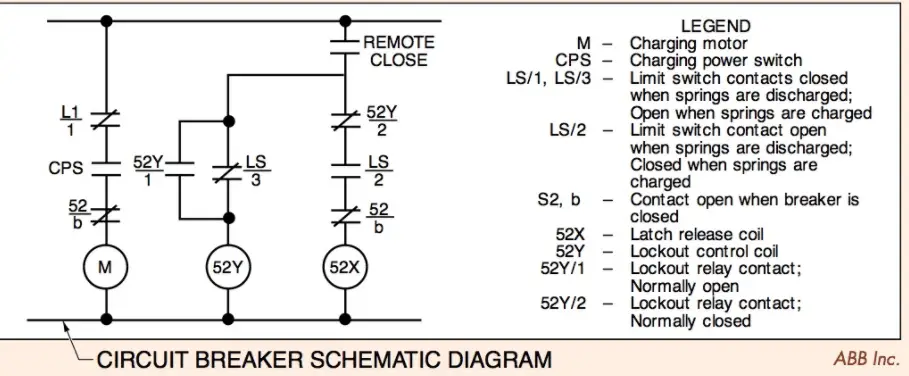
SCHEMATIC DIAGRAMS —ABB
When the circuit breaker is racked into a cubicle and is connected to control power, the following occurs:
- The spring charging motor immediately runs.
- The closing springs charge.
- Contact limit switches 1 and 3 (LS1 and LS3) open and shut off the motor.
- Contact LS2 closes and enables 52X (closing control coil).
- Contact 52b is closed because the circuit breaker is open.
The circuit breaker is now enabled to close and will remain in this condition until the CLOSE button is pressed. It is typical for the remote operating switch, identified as “Remote Close” on this drawing, to have a contact that stays closed when operated, as opposed to a momentary close contact. This means that control power is available to the circuit at all times that the control switch is in the closed position. When the remote close switch is operated, the following occurs:
- The circuit breaker main contacts close and discharge the closing springs.
- LS1 and LS3 close, but the motor circuit is disabled by 52b, which is now open.
- LS2 opens and disables the closed circuit.
- LS3 closing energizes 52Y (anti-pump coil), which in turn closes 52Y/1 and opens 52Y/2.
- Contact 52Y/1 forms a parallel path, known as a seal-in circuit, around LS3. This keeps 52Y coil energized until control power is removed.
- Contact 52Y/2 remains open as long as the anti-pump (lockout) coil is energized. The circuit breaker remains in this condition until it trips. When it does the trip, the following occurs:
- Contact 52b recloses.
- LS1 and LS3 close and LS2 open.
- LS1 allows the spring-charging motor to charge the springs, causing LS1 and LS3 to open and LS2 to close.
During this sequence, 52Y remains energized due to the seal-in contact (52Y/1). Ordinarily, the circuit breaker would now be enabled to close, but 52Y prevents this by keeping the 52Y/2 contact open. To close the circuit breaker, control power would have to be removed by resetting the remote close switch to the open position. As a result, 52Y would be de-energized, which would close 52Y/2 and open 52Y/1.
General Electric Circuit Breaker Schematic Diagram
In a General Electric Power/Vac medium-voltage circuit breaker schematic diagram, the circuit breaker is shown de-energized with the circuit breaker open and no control power applied.
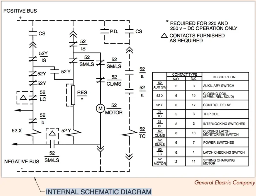
SCHEMATIC DIAGRAMS —GENERAL ELECTRIC
When control power is applied, the following occurs:
- The spring charging motor (M) energizes.
- Coil 52Y energizes (prevents a closing operation until the springs are charged).
- When the springs are charged, 52/SM/LS locations open.
- Since the control switch (CS) is open, 52Y de-energizes.
The circuit breaker is now in a position to close. To close the circuit breaker, the remote CS is turned to the closed position. In the closed position, the following occurs:
- Closing coil 52X becomes energized and releases the closing springs.
- 52 SM/LS locations close because the springs are discharged.
- Auxiliary contact 52b in the closing control circuit changes position as well as the 52a contacts in the trip circuit
- Coil 52Y is energized. Three contacts change position, which opens the circuit to 52X and close the 52Y seal-in contact.
When the breaker is fully set in the closed position, 52/ CL/MS closes, allowing the spring-charging motor to operate. When the springs are charged, 52/ SM/LS opens, stopping the spring-charging motor. As long as the remote control switch contacts remain closed, 52Y is energized, preventing repeated automatic reclosing (anti-pump). To trip or open the circuit breaker once the circuit breaker is closed, the following must occur:
- Both 52a contacts are closed because the circuit breaker is closed.
- Terminals 9 (+) and 10 (–) are connected to the DC voltage source.
- Closing CS/T energizes 52/TC (trip coil), opening the circuit breaker.
Westinghouse/Cutler-Hammer Circuit Breaker Schematic Diagram
In a Westinghouse/Cutler-Hammer schematic diagram, the circuit breaker is shown open, and the closing springs are shown discharged. As soon as power is applied to the control circuit (terminals 7 and 4), the spring charging motor is energized, and the closing springs charge. Once the springs are charged, the limit switch (LS) changes from the closed position to the open position on wire 67, and the LS contact in wire 65/66 closes. This disables the spring charging motor and enables the closing circuit.
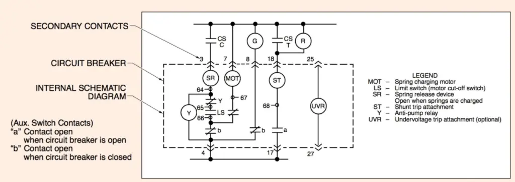
SCHEMATIC DIAGRAMS —WESTINGHOUSE
At this point, the anti-pump coil is short-circuited because the normally open LS contact closes. The “b” contacts are closed when the circuit breaker main contacts are open. When the CS is closed, the following occurs:
- The spring release (SR) coil is energized and allows the circuit breaker main contacts to close.
- Both limit switches change position. The spring charging circuit is enabled, and the spring release coil is disabled.
- Both “b” contacts open. One contact de-energizes the green light, while the other contact disables the spring charging motor, anti-pump coil, and spring release coil.
- The close contact in the CS remains closed, even when the handle is released, as it is a maintain contact.
- The “a” contact on wire 68 closes, which enables the shunt trip (ST) coil.
- The red indicator light illuminates.
The circuit breaker remains in this state until the trip coil is energized by a relay operation. When the trip coil is energized, the circuit breaker main contacts open, which closes both b contacts. The green light illuminates, and the spring charging motor is energized, which charges the closing springs.
When the springs are charged, both LSs change position. One LS de-energizes the motor, and the other energizes the anti-pump coil (Y). The spring release is not energized at this time because the Y contact opens and disables the spring release coil. The Y coil is energized because the CS closed contact is a maintain contact. A maintain contact stays closed even though the CS handle is released. If the CS is turned to the trip position, it will open the close/maintain contact in the CS, and the circuit breaker cannot close automatically.
The CS must be reset to the trip position at this time to reclose the circuit breaker. To trip the circuit breaker open, the trip coil (ST) is connected directly between the positive and negative power terminals. Once 52a contact closes (when the circuit breaker closes), the CS can be operated to the trip position. This will trip the circuit breaker and open the close/maintain contact with the CS.