Learn about what power quality is and different power quality problems in the distribution network such as single phasing, voltage fluctuation, power factor, improper phase sequence, voltage unbalance, and voltage surge.
Correcting power quality problems requires an understanding of all power distribution system components and how a problem in one component can cause problems in other components. Distribution system components include transformers, distribution lines, switchboards, and panel boards, disconnects, circuit breakers, fuses, and receptacles to deliver, control, and protect the system.
Electrical power distribution systems must deliver quality power to loads if the loads are to operate properly for their rated lifetime and performance.
What is a Power Quality?
Quality power is power delivered to a load that is within the load specified voltage, is capable of delivering enough current under any operating condition, and includes minimal, not damaging, changes.
Poor quality power is power delivered to a load that includes excessive or damaging changes such as voltage drops, voltage unbalance, voltage fluctuations, current unbalance, transients, and harmonic distortion. See Figure 1.
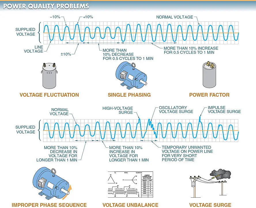
Figure 1. Most Common Power Quality Problems in Power Distribution System
Single Phasing
Single phasing is the operation of a motor that is designed to operate on three phases but is only operating on two phases because one phase is lost.
Single phasing occurs when one of the three lines leading to a 3φ motor does not deliver voltage to the motor. Single phasing is the maximum condition of voltage unbalance in a distribution system.
Single phasing occurs when one phase opens on either the primary or secondary power distribution system. A phase opens when one fuse blows, when there is a mechanical failure within the switching equipment, or when lightning takes out one of the lines.
Single phasing can go undetected in some systems because a 3φ motor running on two phases can still run in low torque applications. A motor that is single phasing will draw all of its current from two lines.
Voltage measurements taken at a motor do not normally indicate a single-phasing condition. The open winding in the motor generates voltage almost equal to the phase voltage that is lost. In this case, the open winding acts as the secondary of a transformer, while the two windings connected to power act as the primary.
Single phasing is reduced through the use of properly sized dual-element fuses and heaters. An electronic phase-loss monitor is used to detect phase loss in motor circuits and other types of circuits in which a single-phasing condition cannot be allowed to exist for even a short period of time. The monitor activates a set of contacts to drop out the starter coil when a phase loss is detected.
The severe blackening of one delta winding or two wye windings of the three 3φ windings will be observable when a motor has failed due to single phasing. The coil or coils that experienced the voltage loss will be in the best condition. The damage occurs in the other coils because of overcurrent. See Figure 2.
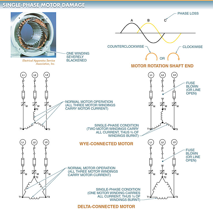
Figure 2. Single-phasing causes severe burning and distortion to one or two windings depending on the configuration.
Single phasing is distinguished from voltage unbalance by the severity of the damage. Voltage unbalance causes less blackening (but over more windings, normally) than single phasing and little or no distortion. Single phasing causes burns and distortion to one winding.
Improper Phase Sequence
Improper phase sequence is the changing of the sequence of any two phases (phase reversal) in a 3φ motor circuit. Improper phase sequence reverses the motor rotation. Reversing motor rotation can damage driven machinery or injure personnel.
Phase reversal can occur when modifications are made to a power distribution system or when maintenance is performed on electrical conductors or switching equipment.
The NEC® requires phase reversal protection on all personnel transportation equipment such as moving walkways, escalators, and ski lifts. See Figure 3.
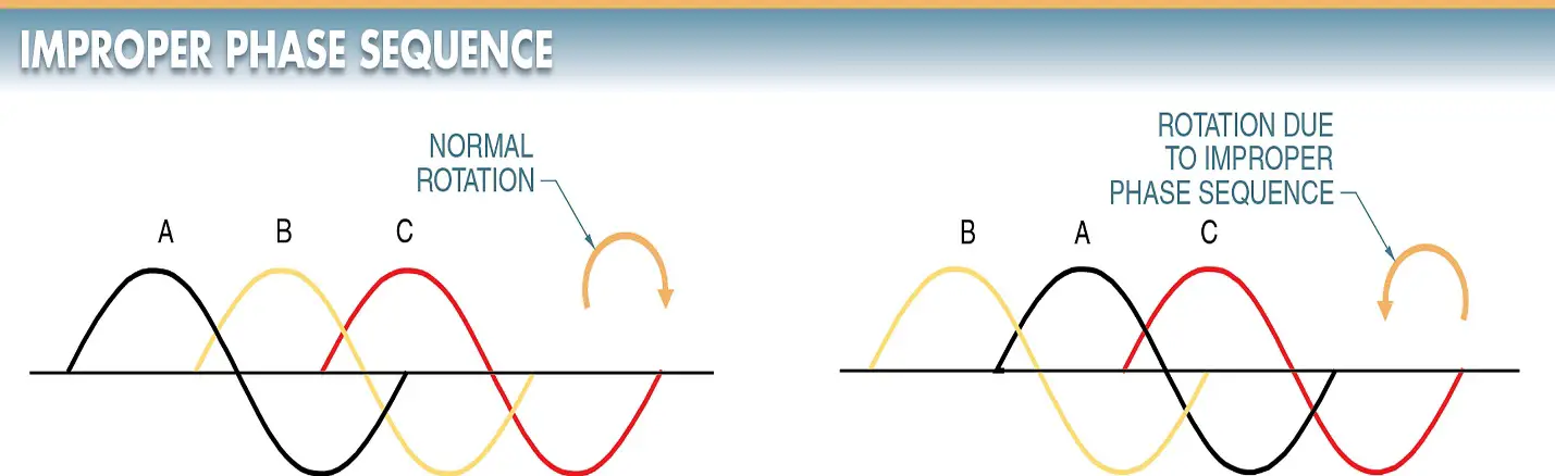
Figure 3. Improper phase sequence is the changing of the sequence of any two phases (phase reversal) in a 3φ motor circuit.
Phase Unbalance
Phase unbalance is the unbalance that occurs when power lines are out of phase. Phase unbalance of a 3φ power system occurs when 1φ loads are applied, which causes one or two of the lines to carry more or less of the load. An electrician balances the load of a 3φ power system during the installation process.
A power quality meter can be used to check phase unbalance on power lines. An unbalance begins to occur when additional 1φ loads are added to the system. This unbalance causes the 3φ lines to move out of phase so the lines are no longer 120 electrical degrees apart. See Figure 4.
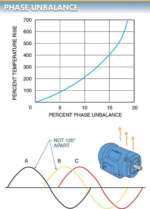
Figure 4. Phase unbalance is the unbalance that occurs when power lines are out of phase.
Phase unbalance causes 3φ motors to run at temperatures higher than their listed ratings. The greater the phase unbalance, the greater the temperature rise. High temperatures cause insulation breakdown and other related problems.
A 3φ motor operating in an unbalanced circuit cannot deliver its rated horsepower. For example, a phase unbalance of 3% causes a motor to work at 90% of its rated power. This requires the motor to be derated. See Figure 5.
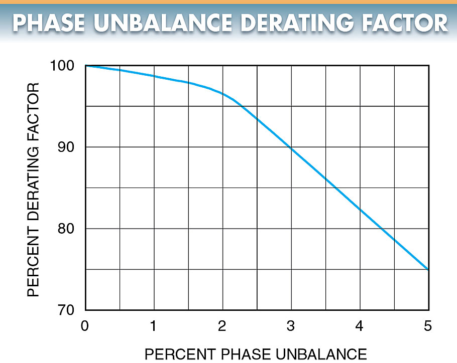
Figure 5. A motor operating on a circuit that has phase unbalance must be derated.
AC Voltage Variations
Motors are rated for operation at specific voltages. Motor performance is affected when the supply voltage varies from a motor’s rated voltage. A motor operates satisfactorily with a voltage variation of ±10% from the voltage rating listed on the motor nameplate. See Figure 6.
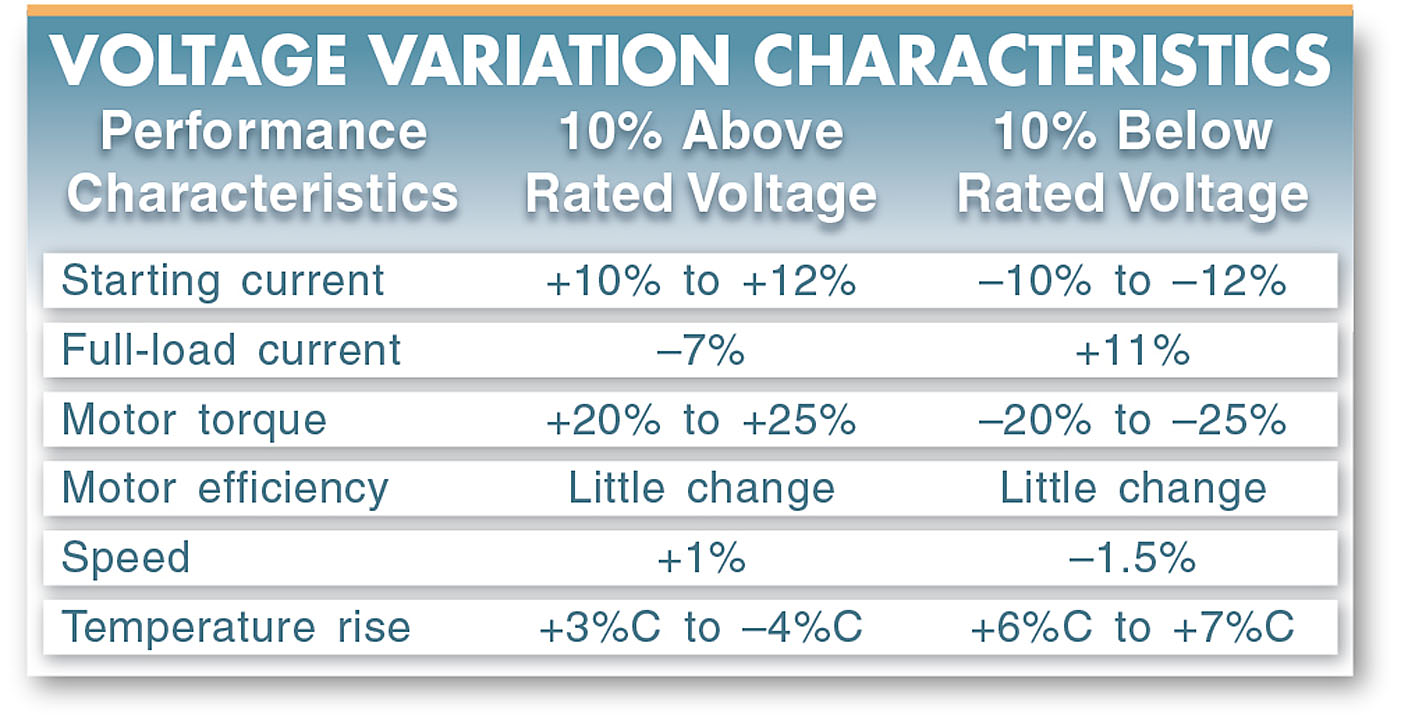
Figure 6. A motor operates satisfactorily with a voltage variation of ±10% from the voltage rating listed on the motor nameplate.
AC Frequency Variations
Motors are rated for operation at specific frequencies. Motor performance is affected when the frequency varies from a motor’s rated frequency. A motor operates satisfactorily with a frequency variation of ±5% from the frequency rating listed on the motor nameplate. See Figure 7.
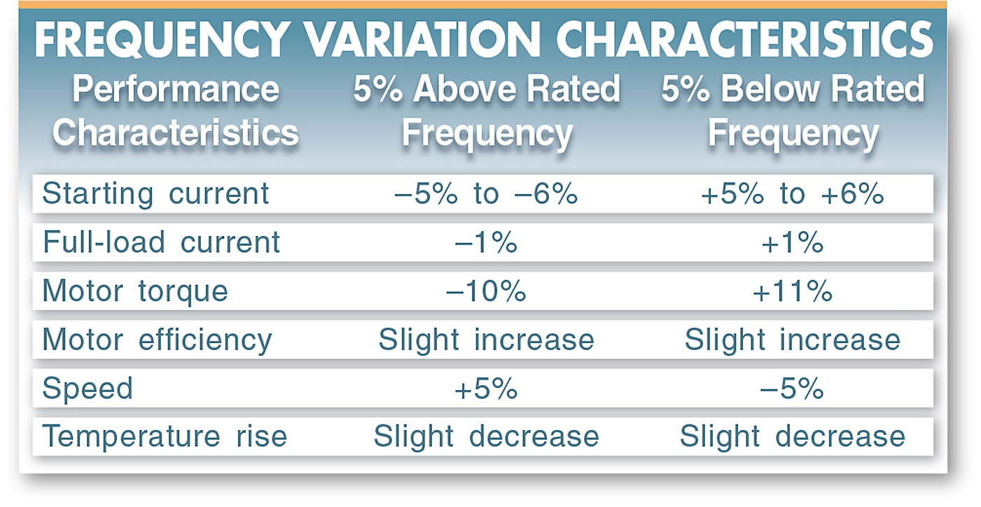
Figure 7. A motor operates satisfactorily with a frequency variation of ±5% from the frequency rating listed on the motor nameplate.
DC Voltage Variations
DC motors should be operated on pure DC power. Pure DC power is power obtained from a battery or DC generator. DC power is also obtained from rectified AC power. Most industrial DC motors obtain power from a rectified AC power supply. DC power obtained from a rectified AC power supply varies from almost pure DC power to half-wave DC power.
DC motor operation is affected by a change in voltage. The change may be intentional, as in a speed-control application, or it may be caused by variations in the power supply.
The power supply voltage normally should not vary by more than 10% of a motor’s rated voltage. Motor speed, current, torque, and temperature are affected when the DC voltage varies from the motor rating. See Figure 8.
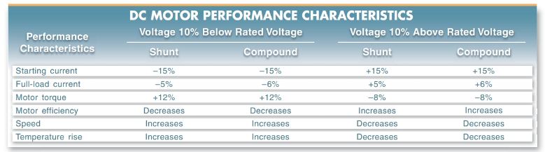
Figure 8. Motor speed, current, torque, and temperature are affected if the DC voltage varies from the motor rating.
Voltage Surges
A voltage surge is a higher-than-normal voltage that temporarily exists on one or more power lines. Lightning is a major cause of large voltage surges.
A lightning surge on a power line comes from a direct lightning hit or induced voltage. The lightning energy moves in both directions on the power lines, much like a rapidly moving wave.
A traveling surge of lightning energy causes a large voltage rise in a short period of time. The large voltage is impressed on the first few turns of the motor windings, destroying the insulation and burning out the motor.
An electrician will be able to observe the burning and opening of the first few turns of the windings that occur when a motor has failed due to a voltage surge. The rest of the windings will appear normal, with little or no damage. See Figure 9.
Lightning arresters with the proper voltage rating and connection to an excellent ground ensure maximum voltage surge protection.
Surge protectors are also available. Surge protectors are placed on equipment or throughout the distribution system.
Voltage surges can also occur due to the normal switching of high-power circuits. Voltage surges that occur due to the switching of high-power circuits are of lesser magnitude than lightning strikes and normally do not cause motor problems. A surge protector should be used on computer equipment circuits to protect sensitive electronic components.
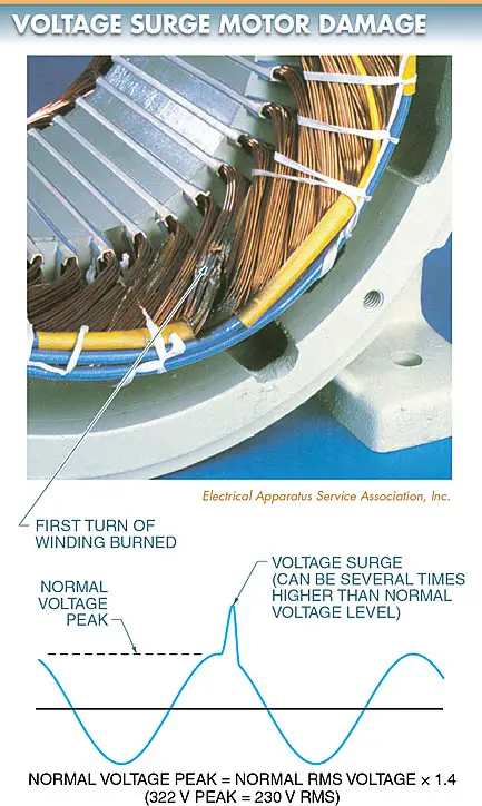
Figure 9. A voltage surge causes burning and opening of the first few turns of the windings.
Tech Fact
Never assume that phase A, phase B, and phase C are the same throughout a structural distribution system. Instead, a phase sequence test instrument is used to identify which lines are powered and which power lines are phase A, phase B, and phase C.
Voltage Unbalance
Voltage unbalance, also known as voltage imbalance, is the unbalance that occurs when voltages at the terminals of an electric motor or other 3φ load are not equal.
Voltage unbalance causes motor windings to overheat, resulting in thermal deterioration of the windings. When a 3φ motor fails due to voltage unbalance, one or two of the stator windings become blackened. See Figure 10.
The problem with voltage unbalance within a power distribution system is that a small amount of voltage unbalance can cause a high current unbalance in loads such as electric motors.
In general, voltage unbalance should not be more than 1%. Whenever there is a 2% or greater voltage unbalance, corrective action should be taken. This may include repositioning loads to balance the current draw on the three power lines if the problem is within the building. The problem is within the building if the unbalance deteriorates when loads are ON and improves when loads are OFF.
If the unbalance is at the main power entrance at all times, the problem is most likely with the utility system and the utility company should be notified.
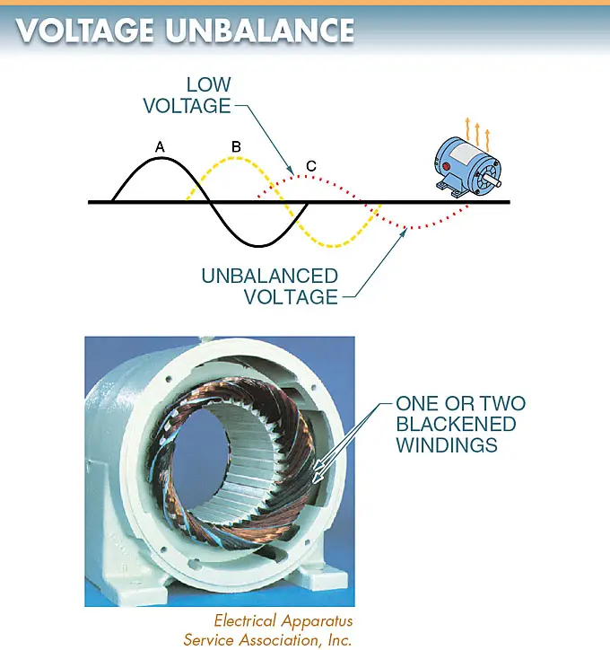
Figure 10. Voltage unbalance within a power distribution system can cause high current unbalance in loads such as electric motors.
Voltage unbalance can be determined through the use of a test instrument or meter.
- First, the meter is set to measure AC voltage for an AC circuit or DC voltage for a DC circuit.
- Next, the meter is tested on a known energized source to verify that the meter is in proper working condition before measurements are taken.
- Then, to find voltage unbalance, the following procedure is applied:
- Measure the voltage between each incoming power line. The readings are taken from L1 to L2, L1 to L3, and L2 to L3. See Figure 11.
- Add the voltages.
- Find the voltage average by dividing the sum of the voltages by 3.
- Find the voltage deviation by subtracting the voltage average from the voltage with the largest deviation.
- Find voltage unbalance by applying the following formula:
\[{{V}_{u}}=\frac{{{V}_{d}}}{{{V}_{a}}\times 100}\]
Where
Vu = voltage unbalance (in %)
Vd = voltage deviation (in V)
Va = voltage average (in V)
100 = percentage
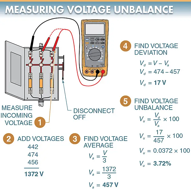
Figure 11. Voltage unbalance is the unbalance that occurs when the voltages at different motor terminals are not equal.
Example: Calculating Voltage Unbalance
Calculate the voltage unbalance of a feeder system with the following voltage readings: L1 to L2 = 442 V, L1 to L3 = 474 V, and L2 to L3 = 456 V.
1. Measure the voltage between each incoming power line.
Incoming voltages are 442 V, 474 V, and 456 V.
2. Add the voltages.
442 V + 474 V + 456 V = 1372 V
3. Find the voltage area.
${{V}_{a}}=\frac{V}{3}=\frac{1372}{3}=457V$
4. Find the voltage deviation.
${{V}_{d}}=V-{{V}_{a}}=474-457=17V$
5. Find voltage unbalance.
\[{{V}_{u}}=\frac{{{V}_{d}}}{{{V}_{a}}\times 100}=\frac{17}{457\times 100}=3.72 \%\]
An electrician will be able to observe the blackening of one delta stator winding or two wye stator windings that occurs when a motor has failed due to voltage unbalance. The winding with the largest voltage unbalance will be the darkest.
Current Unbalance
Current unbalance, also known as current imbalance, is the unbalance that occurs when the currents on each of the three power lines of a 3φ power supply are not equal.
Current unbalance from overloading one or two of the 3φ power lines can cause voltage unbalances. This can cause voltage unbalances on all loads connected within a building.
A 2% voltage unbalance can cause an 8% or higher current unbalance. Current unbalances should not exceed 10%. Any time current unbalance exceeds 10%, the system should be tested for voltage unbalance. Likewise, any time a voltage unbalance is more than 1%, the system should be tested for a current unbalance.
Current unbalance is determined in the same manner as voltage unbalance, except that current measurements are used. See Figure 12.
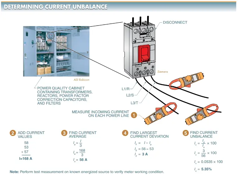
Figure 12. Current unbalance is determined in the same manner as voltage unbalance, except that current measurements are used.
Current unbalance can be determined through the use of a test instrument or meter.
- First, the meter is set to measure AC current for an AC circuit or DC current for a DC circuit.
- Next, the meter is tested on a known energized source to verify that the meter is in proper working condition before measurements are taken.
- Then, to find the percentage of current unbalance in a circuit, the following procedure is applied:
- Measure current on each of the incoming power lines.
- Add all current values together.
- Calculate the current average by taking the sum of current measurements and dividing by the number of measurements taken.
- Calculate the largest current deviation by subtracting the lowest current measurement from the current average.
- Calculate the current unbalance by dividing the largest current deviation by the current average and multiplying by 100.
Example: Calculating Current Unbalance
Calculate the current unbalance of a feeder system with the following current readings: L1=58A, L2=53A, and L3=57A.
1. Measure the current for each incoming power line.
Incoming currents are 58 A, 53 A, and 57 A.
2. Add the currents
58 A + 53 A + 57 A = 168 A
3. Find the current average.
${{V}_{a}}=\frac{V}{3}=\frac{168}{3}=56A$
4. Find the current deviation.
${{I}_{d}}=I-{{I}_{a}}=56-53=3A$
5. Find current unbalance.
\[{I_u} = \frac{{{I_d}}}{{{I_a} \times 100}} = \frac{3}{{56 \times 100}} = 5.35\% \]
Power Quality Takeaways
Understanding Power Quality: Power quality refers to the characteristics of electrical power supply, including voltage stability, frequency stability, waveform distortion, and interruptions. It is crucial for ensuring efficient and reliable operation of electrical systems and equipment.
Voltage Fluctuations: Power quality issues often manifest as voltage fluctuations, including voltage sags (temporary decreases), voltage swells (temporary increases), and voltage harmonics (distorted waveforms). These fluctuations can cause equipment malfunctions, data loss, and production disruptions.
Frequency Variations: Deviations in the power frequency can also affect the performance of electrical devices. Frequency variations can lead to synchronization problems, inefficient motor operation, and inaccurate timing in sensitive equipment.
Harmonic Distortion: Harmonics are unwanted frequency components that result from non-linear loads in electrical systems, such as computers, variable speed drives, and power electronics. Harmonic distortion can lead to overheating of equipment, reduced system efficiency, and interference with sensitive electronic devices.
Transients and Surges: Power quality issues also include voltage transients and surges, which are short-duration fluctuations in voltage levels. These events can cause equipment damage, data corruption, and even complete failure if not properly mitigated.
Power Factor: Power factor is a measure of how effectively electrical power is being used. A low power factor can lead to increased energy consumption, higher utility costs, and reduced system capacity.
Importance of Power Quality Monitoring: Continuous power quality monitoring is essential for identifying and resolving power quality issues promptly. Monitoring systems can capture data on voltage, current, harmonics, and other parameters, enabling proactive maintenance and troubleshooting.
Mitigation Techniques: Various mitigation techniques can help address power quality issues. These include installing power factor correction capacitors, implementing harmonic filters, employing voltage regulation devices, and ensuring proper grounding and shielding practices.
Standards and Regulations: Several international standards and regulations govern power quality, such as IEEE 519, IEC 61000 series, and EN 50160. Compliance with these standards helps ensure acceptable power quality levels and promotes reliable and efficient operation of electrical systems.
Collaboration and Expertise: Power quality issues require collaboration between electrical utilities, equipment manufacturers, and end-users. Engaging power quality experts and consultants can provide valuable insights, assessments, and solutions to optimize power quality and mitigate potential problems.
In summary, power quality is crucial for the reliable and efficient operation of electrical systems. Understanding and addressing power quality issues through monitoring, mitigation techniques, and adherence to standards is essential for minimizing equipment damage, optimizing energy consumption, and ensuring the smooth functioning of electrical systems.
Power Quality FAQs
What is power quality?
Power quality refers to the characteristics of electrical power supply, including voltage stability, frequency stability, waveform distortion, and interruptions. It encompasses factors that affect the quality and reliability of electrical power.
Why is power quality important?
Power quality is crucial for the efficient and reliable operation of electrical systems and equipment. Poor power quality can result in equipment malfunctions, data loss, production disruptions, increased energy consumption, and higher maintenance costs.
What are common power quality issues?
Common power quality issues include voltage fluctuations (sags, swells), harmonic distortion, frequency variations, transients, surges, and power factor problems. These issues can impact the performance and lifespan of electrical equipment.
How can voltage fluctuations affect equipment?
Voltage fluctuations, such as sags and swells, can cause equipment malfunctions, premature wear and tear, data corruption, and production interruptions. Sensitive electronic devices are particularly vulnerable to voltage fluctuations.
What are harmonics, and why are they a concern?
Harmonics are unwanted frequency components that result from non-linear loads in electrical systems. Harmonic distortion can lead to overheating of equipment, reduced system efficiency, and interference with sensitive electronic devices.
How can power quality be improved?
Power quality can be improved through various measures such as power factor correction, harmonic filtering, voltage regulation, proper grounding and shielding practices, and adherence to power quality standards and regulations.
How can power quality issues be identified?
Power quality issues can be identified through continuous monitoring of voltage, current, harmonics, and other parameters. Power quality monitoring systems provide valuable data for analyzing and troubleshooting power quality problems.
Are there standards and regulations for power quality?
Yes, there are international standards and regulations that govern power quality, such as IEEE 519, IEC 61000 series, and EN 50160. Compliance with these standards ensures acceptable power quality levels and promotes reliable operation of electrical systems.
How can businesses and industries address power quality concerns?
Businesses and industries can address power quality concerns by collaborating with electrical utilities, consulting power quality experts, implementing mitigation techniques, conducting regular maintenance, and investing in quality electrical equipment.
What are the benefits of maintaining good power quality?
Maintaining good power quality results in improved equipment performance, extended equipment lifespan, reduced downtime, energy savings, lower maintenance costs, and increased productivity and operational efficiency.