In this article, we will look at how residential service entrances, switches, and receptacles are connected to form the basic residential electrical circuit.
Conductor
Most residential electrical circuits utilize one of the conductor combinations identified in Table 1. The conductor combinations listed are illustrated in Figure 1.
Table 1: Conductor Combinations
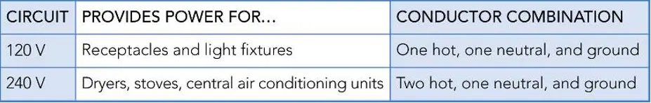
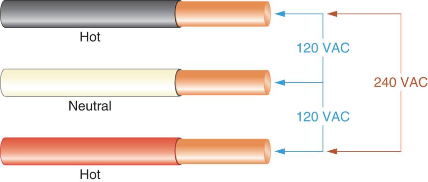
Figure 1: Conductor Voltages in 240-V Electrical Circuit
The current level that each conductor in Figure 1 can handle depends on its gauge. For example,
• 14 gauge wires can handle currents up to 15A
• 12 gauge wires can handle currents up to 20A
• 10 gauge wires can handle currents up to 30A
• 8 gauge wires can handle currents up to 40A
Note that these statements indicate current handling capabilities only. They do not take into consideration any local building code restrictions. Note also that a wire can be substituted for a smaller diameter (higher gauge) wire, but not for a larger diameter (lower gauge) wire. For example, 12 gauge wire can be used in place of 14 gauge wire in the 15A circuit. However, 12 gauge wire cannot be used in place of 10 gauge wire in a 30A circuit.
Nonmetallic Cables
A nonmetallic (NM) cable (also called Romex cable) is a group of insulated conductors housed in a protective plastic jacket. The lower nonmetallic cable shown in Figure 2 contains a hot conductor a neutral conductor, and a bare ground wire. As indicated in Table 1, this cable is well suited for use in a 120V circuit. The upper NM cable in Figure 2 has two hot conductors, a neutral conductor, and a bare ground wire. As such, it is well-suited for use in a 240 V circuit.
The label on an NM cable indicates the size (gauge) and a number of conductors in the cable. For example, the label:
14/2 w/GR
(“Fourteen/two with ground”) indicates that the cable contains two 14 gauge conductors and a ground wire. By the same token, the label:
12/3 w/GR
(“twelve/three with ground”) indicates that the able contains three 12 gauge conductors and a ground wire.
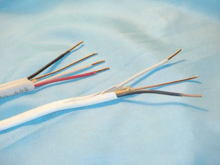
Figure 2: Non-metallic Cable
The cable type—either NM or NMC—indicates the suitability of the cable cover for use in different environments. For example, type NMC cable is better suited than type NM cable for use in wet environments. Consequently, type NM cable installed in dry locations (such as interior walls), while NMC cable is typically installed in masonry and other damp locations.
Another type of cable that can be used in place of NM cable is housed in a flexible metal cover. This type of cable is often referred to as BX cable or armored cable but is properly called type AC cable. Type AC cable with an additional external plastic sheath is called TECK cable. It is also common practice to run NM cable in a rigid metal conduit if it is not inside the wall or otherwise protected.
A Typical 120 V Residential Electrical Circuit
As indicated earlier, most 120V circuits are used to provide power to one or more receptacles and/or light fixtures. A circuit containing two receptacles, a switch and a light fixture is illustrated in Figure 3. The circuit originates with a 15A breaker in the service panel (not shown). The breaker is in series with both receptacles, the switch, and the light fixture to enable it to cut power to the entire circuit if an overcurrent event occurs.
An NM cable extends from the breaker to one receptacle, and the second receptacle is connected in parallel with the first. From there, the cable continues to a single pole switch that controls the light fixture. Note that both receptacles and the light fixture are wired in parallel with each other and with the rest of the circuit.
This is a very important point. As you know, one of the characteristics of the parallel circuit is that all branches in the circuit have the same voltage. Think what would happen if all the receptacles in the house were not wired in parallel. If you were to turn on the TV, the voltage drop across the TV would affect every device connected in series with it.
Every device that we connect to a 120V receptacle expects to get 120V, so all 120V receptacles are wired in parallel with each other.
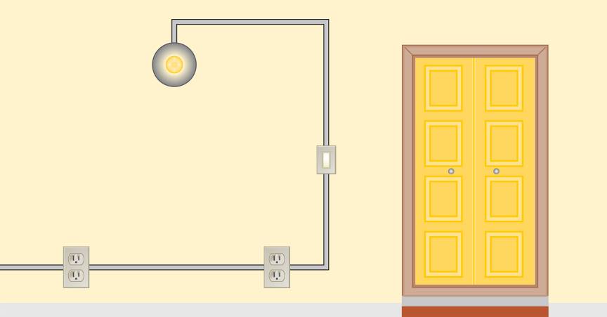
Figure 3: A Typical 120-V Electrical Circuit
The switch, on the other hand, is connected in series with the light fixture, as t must make or break a connection between the light and the receptacle. It cannot be in parallel with the light fixture, and it cannot be in series with any of the outlets unless you want the outlets to be turned off and on with the light.
The wiring of each receptacle in Figure 3 is illustrated in Figure 4. As you can see, two sets of hot and neutral conductors are connected to a receptacle.
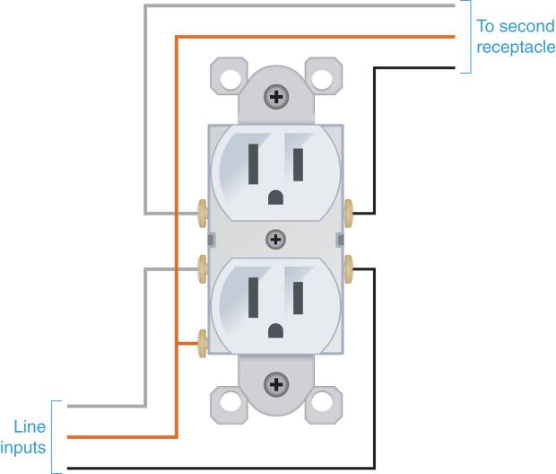
Figure 4: Receptacle Connections
One set is connected to a 15A breaker in a service panel while the other continues on to the second receptacle, the switch, and the light fixture. Note that the wires can be connected o the receptacle by using the hot and neutral screws (as shown in the figure), or by using the “push in” connectors on the back of the receptacle.
The wiring of the single-pole switch is illustrated in Figure 5. The switch is inserted in series with the “hot” line, while the neutral conductor bypasses the switch altogether. Again, it is important that the switch is wired in series with the hotline, not the neutral line. Breaking the grounded neutral line still leaves the circuit energized if another path to ground is provided.
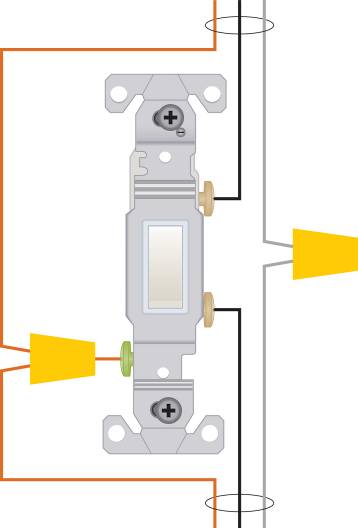
Figure 5: light Switch Connections
The light fixture in Figure 3 is wired as shown in Figure 6. Because this is the final element in the circuit, the conductors do not continue beyond the fixture. Note that the series combination of the switch and the light fixture are in parallel with the two receptacles. The 15A breaker back at the panel as in series with the parallel connected receptacles and the light switch/fixture circuit. So the breaker, the receptacles, the light switch, and the fixture all for a series-parallel circuit.
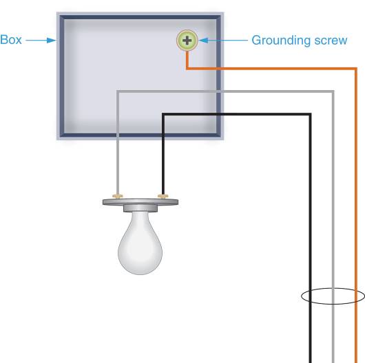
Figure 6: Light-Fixture Connections
A Typical 240 V Residential Electrical Circuit
A typical 240V circuit is illustrated in Figure 7. The circuit shown provides 240 to the receptacle for an electric dryer. The nonmetallic (NM) cable –which is labeled “10/3w/GR” —originates at a 30A double throw breaker pair and provides 240V for the dryer receptacle.
As is always the case for a breaker or fuse, the circuit protectors (breaker or fuse) must be in series with the circuit if it is to break the circuit whenever an overcurrent situation develops.
One side of the breaker is in series with one hot conductor and the other side of the breaker is in series with the other hot conductor. The cable is connected to the receptacle as shown in Figure 8.
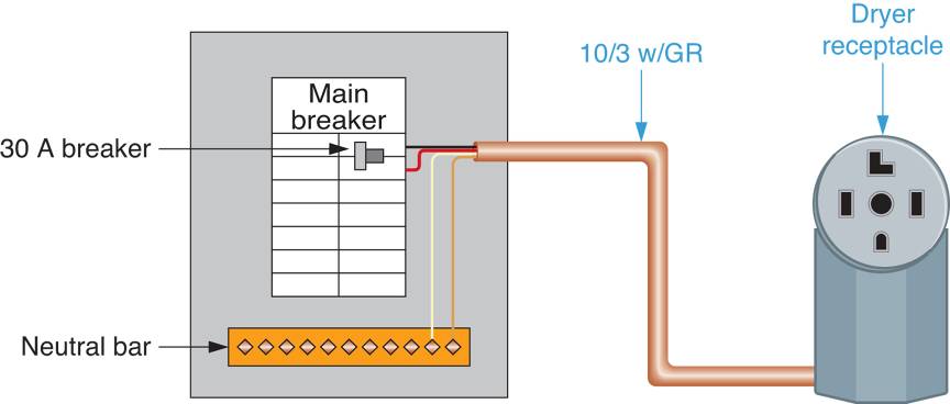
Figure 7: A 240-V Circuit
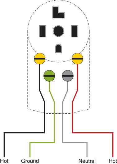
Figure 8: Internal connections for the receptacle in Figure 7
Summary
- Most residential electrical circuits utilize one of the following conductor combinations:
- One hot, the neutral, and a ground, used for 120-V receptacles and light fixtures
- Two hotlines, one neutral, and one ground, used for 240-V appliances like stoves, dryers, and air conditioners.
- The current level that conductor can handle is determined by its gauge.
- 14 gauge wire handles currents up to 15 A
- 12 gauge wire handles currents up to 20 A
- 10 gauge wire handles currents up to 30 A
- 8 gauge wire handles currents up to 40 A
- Any lower-gauge wire (larger diameter) wire can be substituted for any higher-gauge wire
- You must never substitute a higher-gauge wire (smaller diameter) for a lower-gauge wire.
- A nonmetallic cable is a group of insulated conductors housed in a protective plastic jacket.
- The label on the outside of the cable indicates its size (gauge) and number of conductors
- For example, the label 14/2 w/GR indicates that the jacket contains two 14 gauge wires and a ground wire.
- The cable type is labeled as NM or NMC
- NM is installed in dry areas like internal walls
- NMC can be used in masonry and other damp locations
- The switch is connected in series with the light fixture
- It is inserted in the hotline, while the neutral bypasses the switch