Power enters the drop through the Service Entrance. The service entrance includes the Electric Meter that measures the amount of energy delivered to the home and the Service Panel that houses the circuit breakers or fuses. The service panel also distributes power to the various circuits in the house.
Service Drop
An overhead power connection from the utility lines to the service entrance is called the Service Drop.
The service drop illustrated in Figure 1 has two 120V lines and a neutral conductor. The three lines may be independent conductors or housed in a three conductor cable called a triplex cable (As shown in the figure).
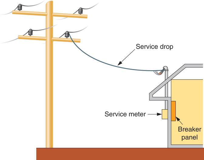
Figure 1: A service Drop
The three conductors comprising the service drop consist of two hotlines and one neutral. Each hotline as a potential of 120V to the neutral line. Between the two hotlines, there is a difference of potential 240V. This is why the service is identified as a 120/240V service. This concept is illustrated in Figure 2.
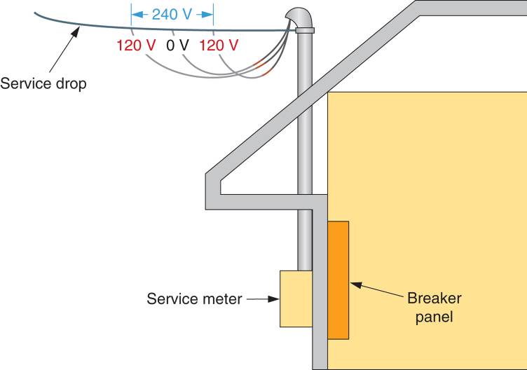
Figure 2: Service Drop Voltages
Mast and Clevis Service Drops
There are two types of overhead service drops, mast, and clevis. A mast service drop is illustrated in Figure 3. The term Mast refers to the conduit and weather head that extend upward from the roof. The service drop is attached to the mast at the mast knob.
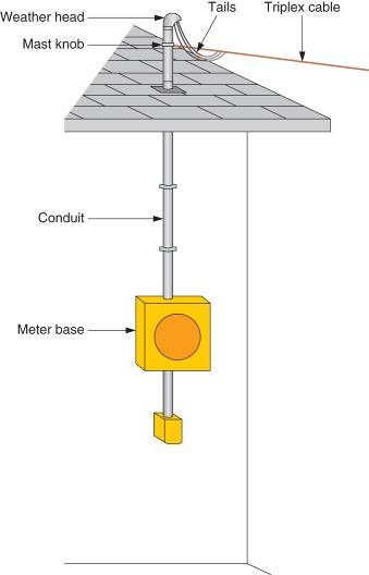
Figure 3: Mast-type Service Drop
The conduct Tails (or drip loops) serve two purposes. Firstly, they provide slack that reduces any mechanical stresses on the power lines. This is referred to as strain relief. Second, they prevent any water (due to rain) from traveling along the lines into the service drop conduit.
A clevis service drop has fasteners that secure the power lines (or triplex cable) to the side of the residence, as shown in Figure 4. The term Clevis refers to the connectors that fasten the conductors to the building. Note that the weather head and conduit are secured to the side of the residence below the roof line. This distinguishes the clevis service drop from the mast service drop.
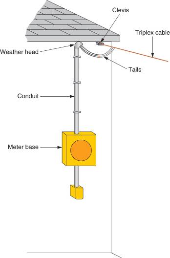
Figure 4: Clevis-Type Service Drop
Service Lateral
An underground service connection, or Service Lateral, is illustrated in Figure 5. The primary power lines pass through the conduit to the pad transformer input. The secondary power lines connect the transformer output to the electrical service meter.
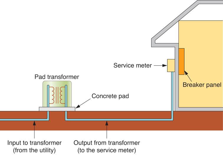
Figure 5: A service lateral
Transformers are devices that are used to raise or lower a voltage level. In this case, the transformer is used to lower the voltage from the utility to the 120/240V residential level.
Service Meter
As stated earlier, the service meter measures the amount of energy that is used by the customer. Two electrical services meters are shown in Figure 6, one providing an analog display (rotary dials) and the other providing digital display.
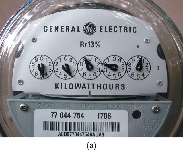
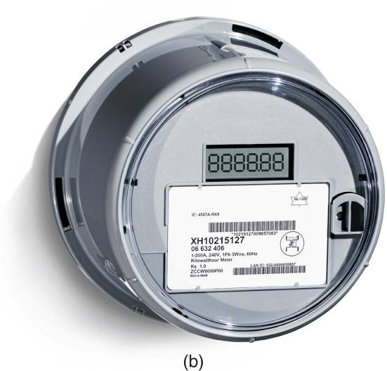
Figure 6: Analog Vs Digital Energy Meter
The electrical service measures energy in Kilowatt-hours (kWh). A kilowatt-hour is the amount of energy used in one hour, found as:
\[\begin{matrix}{{E}_{kWh}}=\frac{P\times t}{1000} & {} & \left( 1 \right) \\\end{matrix}\]
Where
P= power in watts (W)
T= time in hours (h)
1000 in the denominator of the equation converts the power to kilowatts (kW).
The dials on the meter in Figure 6a are read from left to right. The weights of the dials (from left to right) are 10000,1000,100,10, and 1. The values indicated by each dial equals the reading times its weight (the value printed above the dial). For example, the value indicated by the meter in Figure 6a is found as:
$4\times 10000+5\times 1000+9\times 100+2\times 10+0=45,920kWh$
Note that the dials on the analog meter rotate in alternating directions. That is the dial on the left rotates counterclockwise (CCW), the next rotates clockwise (CW) and so on.
There is an important point to be made at this time. In most cases, the electrical service meter is the point where the utility’s responsibility ends. Any repairs required in the service drop or service meter are made by the utility with no charge to the customer. However, any problems beyond the service meter are the customer’s responsibility.
This meter in Figure 6a is an electromechanical meter, while the one shown in Figure 6b is an electronic meter. The electronic meter is essentially a series-parallel circuit that converts the incoming current and voltage to a signal that indicated the amount of energy used.
Main Disconnect
Every residential service entrance must provide a means of disconnecting the electrical power feed in case of an emergency. In some cases, the Main Disconnect switch (or breaker) is an Externally Operated (EXO) Switch that is inserted between the service meter and the electrical panel. An EXO switch is shown in Figure 7. In other cases, one or more circuit breakers are housed in the electrical panel that provides the required main disconnect capability.
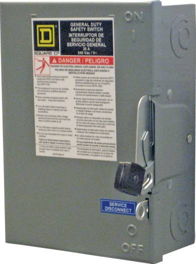
Figure 7: An externally operated (EXO) main disconnect
Regardless of the type of the main disconnect used, the breaker(s) must be in series with both hotlines. The main disconnect must cut power (interrupt current) to all circuits. This can be accomplished only if it is connected in series with them.
The Service Panel
The final element in the service entrance is the service panel. As stated earlier, the service panel performs two important functions:
1. It houses the overload protection components (circuit breakers in most cases, and fuses in older panels)
2. It serves as the connection point between the main Feeder and Branch Circuits.
A typical residential service panel is illustrated in Figure 8.
The power and neutral lines enter the service panel in Figure 8 through the conduit that is secured to the panel. The two hot lines (black and red) are connected to the Main Breaker, a double pole, double throw (DPDT) switch that serves the main disconnect for the service entrance. As in the case with the main disconnect, the main breaker is in series with both hotlines. The neutral conductor (white) is connected to the Neutral Bar (or ground bar), which is the common connection point for all the neutral, or return, lines in the residence. You can think of this as a common ground.
When the main breaker is closed, it connects the feeder conductors to two metal structures called Power Buses, with the black wire being connected to the 120V connections and mounting structures for the remaining circuit breakers. The power buses are configured so that adjacent circuit breakers are connected to alternating buses. For example, in Figure 8, the top circuit breaker is connected to Bus A, then next to Bus B, and so on. This arrangement serves two purposes:
1. By alternating power buses, the loads (residential branch circuits) are balanced between the two service inputs. That is, nearly equal number of circuits draw power from the black power line and red power line.
2. A 240V connection can be made using breakers that are connected to adjacent 120V bus connections. For example, a 240V connection is formed by the top two breakers in Figure 8.
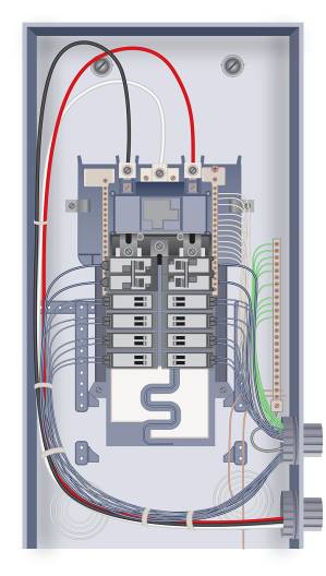
Figure 8: Typical Residential Service Panel
Grounding
A continuous low-resistance ground path is a part of any residential electrical system. This ground path ensures that the voltage levels in a residential wiring system are stable and that the overload protection elements are as effective as possible.
A grounding circuit is illustrated in Figure 9. The incoming neutral line is connected to the neutral bus. The neutral bus, In turn, is connected directly to earth ground using one of two methods:
1. The ground conductor leads from the neutral bar to the water pipes or gas pipes.
2. If neither of the connections in (1) will work, a ground conductor is run from the neutral bar to a Ground Rod outside of the residence.
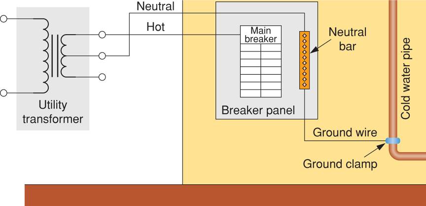
Figure 9: A Grounding Circuit
The ground conductor in Figure 9 leads from the neutral bar to a ground clamp on the water pipe. Because the water pipes go underground the grounding conductor establishes a connection between earth ground and the neutral bar in the service panel. When the neutral wire in a branch circuit terminates at the neutral bar, it becomes the ground conductor for that circuit.
To have a continuous ground path, steps must be taken to make sure that nothing breaks (interrupts) that path. Consequently, a connection must be made around (in parallel with) anything that breaks the ground path. For example, the water meter in Figure 10 breaks the electrical continuity in the water pipe.
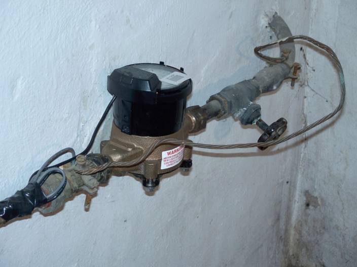
Figure 10: A Grounding Conductor Bypasses a Water Meter
To ensure that the water pipe provides a continuous ground path, a conductor is connected between the water pipes on either side of the meter. This provides a ground connection that bypasses (goes around) the meter.
It should be noted that gas pipes can be used to provide the required grounding connections. In this case, it is the gas meter that will require a bypass conductor like the one shown in Figure 10.
When water or gas pipes cannot be used to provide the required ground connection, a conductor is connected between the neutral bar (in the service panel) and a grounding rod outside the residence as shown in Figure 11.
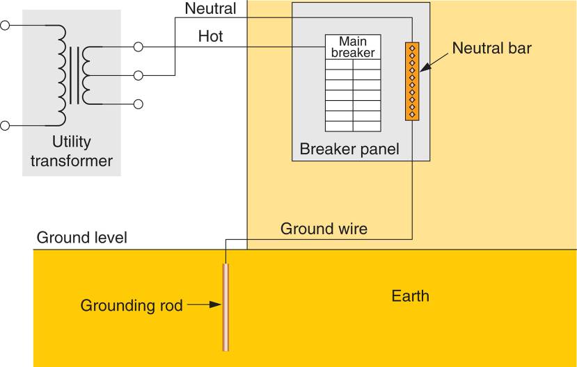
Figure 11: Grounding Rod Connection
Summary
- The service entrance is the place where power enters a residence. It consists of the electric meter and the service panel.
- A mast service drop is an overhead service drop where the service drop is connected to the mast knob. A clevis service drop is also an overhead service drop but the service drop is connected to a clevis or connector. A lateral drop is an underground service drop.
- Drip loops refer to the sag in the service drop before it is connected to the clevis or mast knob. The drip loops prevent water from entering the mast and also provide strain relief.
- The dials on a service meter are read left to right with values of 10,000, 1000, 100, 10 and 1 kWh respectively. Each dial rotates in the opposite direction to the one on either side.
- The main disconnect is a switch that is used to disconnect power from the entire residence in case of an emergency. An EXO is an externally operated switch that is located between the service meter and the electrical panel.
- The service panel is the connection point between the feed and branch circuits. It also houses the overload protection components (fuses or circuit breakers).
- The three conductors are colored black, red, and white. The black and red (hot) conductors are connected to the main breaker and the white is connected to the neutral bar.
- The neutral line is connected to earth ground by connecting it to a grounding rod or to metal underground water or gas pipes.