A three-phase load is a set of three exactly similar combinations of electric components arranged in exactly the same way (in series, parallel or other). The reason to have three-phase loads is the higher power demand.
For instance, in the industry, the majority of motors are three phase, particularly the larger motors that deliver large magnitudes of power to conveyors, pumps, blowers, machine tools, and so on.
The three components in AC are resistors, inductors, and capacitors. In this sense, the three-phase loads can be purely resistive (consisting of heating elements only), resistive and inductive (like electric motors), and resistive, inductive, and capacitive (like many motors that are accompanied by capacitors for various reasons).
Because the three separate sets of loads are identical and are simultaneously connected to electricity, they are balanced. Thus, all three-phase loads automatically form a balanced load for a three-phase circuit.
Dealing with three-phase loads is much simpler than if independent single-phase loads are connected to a three-phase circuit.
- You May Also Read: Three-Phase System Theory Explained | Star and Delta Connection
In fact, many of the relationships and calculations for three-phase loads resemble their counterparts for single-phase systems. This is because the individual parts of the loads on the three phases behave alike. For instance, in a load consisting of resistors and inductors, there is a phase difference between the current and the voltage. For a three-phase load this phase difference is the same for all the three phases, and, as a result, we need to find it for only one phase.
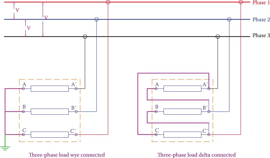
Figure 1 Wye and delta connection of the same load.
For analyzing three-phase loads, we need to know the relationships between voltage, impedance, current, power, and power factor, as well as power factor correction.
Again, here we have three types of power: active power, reactive power, and apparent power. We need, though, to make a distinction between delta connection and wye connection.
A three-phase load can initially be open, with six terminals to deal with. On the basis of how these terminals are connected together and to the external lines they form a wye or a delta connection.
Figure 1 shows how the 6 terminals A, B, C, A′, B′, and C′ can be connected for wye and delta connection. The two methods of connection are not equivalent and affect the current and power taken from a circuit.
Dealing with unbalanced loads is more difficult, and each branch must be individually analyzed and the results are put together.
Three-Phase Relationships for Balanced Loads
Referring to the following figure, which depicts the definition of line and phase currents as well as line and phase voltages for both delta and wye connection of a load, the following relationships always exist:
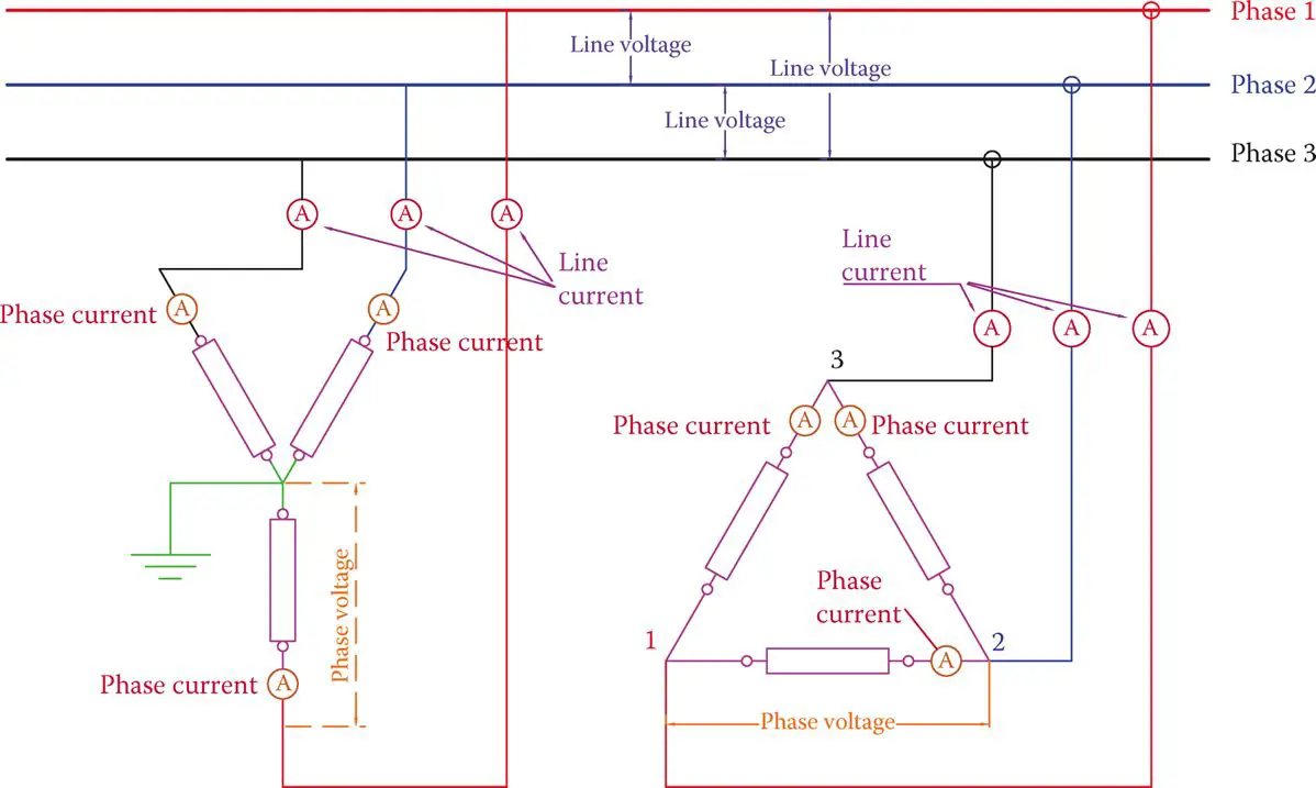
Figure: Definition of phase current and line current.
For wye-connected load,
\[\begin{align} & \begin{matrix} {{I}_{L}}={{I}_{ph}} & {} & \left( 1 \right) \\\end{matrix} \\ & \begin{matrix} {{V}_{L}}=\sqrt{3}{{V}_{ph}} & {} & \left( 2 \right) \\\end{matrix} \\\end{align}\]
For delta-connected load,
\[\begin{align} & \begin{matrix} {{I}_{L}}=\sqrt{3}{{I}_{ph}} & {} & \left( 3 \right) \\\end{matrix} \\ & \begin{matrix} {{V}_{L}}={{V}_{ph}} & {} & \left( 4 \right) \\\end{matrix} \\\end{align}\]
Current in a component can always be found by Ohm’s law. If the impedance of each of the three elements of a three-phase load is denoted by Z, then
\[\begin{matrix} {{I}_{ph}}=\frac{{{V}_{ph}}}{Z} & {} & \left( 5 \right) \\\end{matrix}\]
Equation 1 to 5 can determine all values if two of them are known.
Note that for a balanced load all the phase currents are equal and all the line currents are also equal. Also, referring to Figure 2, although the line currents are equal in magnitude, they cannot be in phase with each other.
As shown, for both the delta-connected load and the wye-connected load, at a given instant while the currents on two phases are toward the load, the current on the third phase is in the opposite direction (remember that in AC electricity the current direction continuously changes; here the direction for current implies that if at a given instant its magnitude is positive or negative).
Because the AC current continuously changes direction, those shown in Figure 2 are momentary values and for one instant later the directions will be different.
We want to say that for a balanced load the three currents have the same relationships as the voltages have. That is, for sinusoidal voltage the variation of currents is sinusoidal and with a phase difference, and moreover, their instantaneous sum is zero.
$\begin{matrix} {{I}_{1}}+{{I}_{2}}+{{I}_{3}}=0 & {} & \left( 6 \right) \\\end{matrix}$
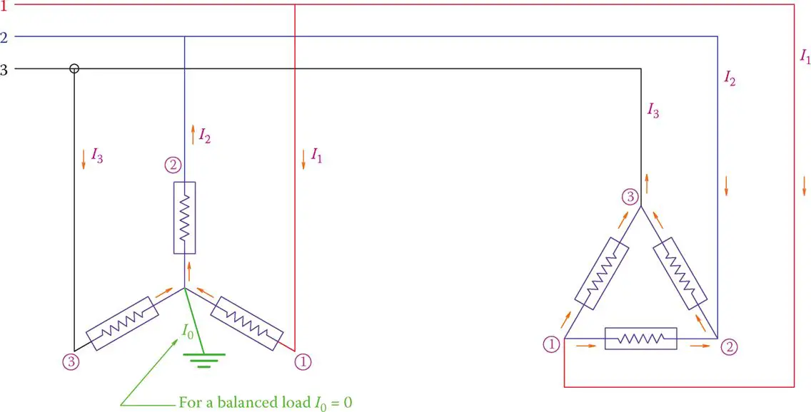
Figure 2 Instantaneous direction of currents in three-phase systems.
Equation 6 implies that at any instant the sum of the currents in the three lines of a three-phase system is zero for balanced loads. In this sense, current I0, associated with the grounded wire or the neutral line (when it is present) is zero. This is the reason why the neutral line is smaller in size than the three-phase lines.
Power in Three-Phase System
The relationships for power for three-phase systems must be separately stated. There are two aspects of power relationships, one is with regards to the three types of power (active, reactive, and apparent), and the other is with regards to the fact that we have phase voltage and phase current versus line voltage and line current.
The relationships between active, reactive, and apparent power can be seen in the following equations:
$\begin{align} & \begin{matrix} PF=\cos \left( phase\text{ }angle \right) & {} & \left( 7 \right) \\\end{matrix} \\ & \begin{matrix} ActivePower\left( P \right)=Apparent\text{ }Power*Power\text{ }Factor=S*PF & {} & \left( 8 \right) \\\end{matrix} \\ & ReactivePower\left( Q \right)=ApparentPower*\sin \left( phase\text{ }angle \right) \\ & \begin{matrix} =S*\sqrt{1-P{{F}^{2}}} & {} & \left( 9 \right) \\\end{matrix} \\\end{align}$
But, then the expression for apparent power S for both delta connection and wye connection of a load is
\[\begin{align} & \begin{matrix} S=\sqrt{3}*{{V}_{L}}*{{I}_{L}} & {} & \left( 10 \right) \\\end{matrix} \\ & Or \\ & \begin{matrix} S=3*{{V}_{ph}}*{{I}_{ph}} & {} & \left( 11 \right) \\\end{matrix} \\\end{align}\]
The two expressions in equations 10 and 11 are equivalent because, in the delta connection, where the phase and line voltage are the same, the line current is √3 times the phase current and in wye connection that the line current and the phase current are the same, the line voltage is √3 times the phase voltage.
Equations 10 and 11 must be used together with equations 8 and 9 in order to avoid any confusion when a load is entirely resistive or entirely reactive.
When a load is entirely resistive, the power factor is 1 and the apparent power and active power are the same.
Likewise, when a load is entirely reactive, for instance, when a set of capacitors are connected to a line, the power factor is zero and the apparent power and the reactive power is the same.
Star-Delta Switch
There are a number of facts that are being used in practical applications. These are
- For the same load, the current in the line and the power consumption are smaller (one third, to be more specific) if the load is connected in wye rather than delta.
- By the same token, a generator can deliver more power if the windings are delta connected.
For the above reasons, in order to reduce the initial current of certain applications, particularly three-phase electric motors that have a high inrush current, a special type of switch is used that connects a three-phase load to electricity in two stages.
In the first stage a wye connection is made by a first turn of the switch, and with a further turn, the connection is changed to Delta. This arrangement is schematically illustrated in Figure 3.
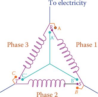
Figure 3 Schematic of a star-delta switch for starting three-phase motors.
First, points R, S, and T, which are the free ends of the load (winding) are connected to A′, B′, and C′. This makes a wye connection, but if R, S, and T are connected to A, B, and C (i.e., what is done after a further turning of the switch), then the load is delta connected to the three-phase line.
Inrush current: Relatively high current that a motor initially experiences when connected to electricity (at zero speed). Current decreases as the motor speeds up.
A star-delta switch, however, is a mechanical system, and it belongs to the technology of the past. Nowadays, this technology is replaced with electronic switching; instead, for starting motors a variable frequency drive (VFD) is employed, which also offers other advantages.
A variable frequency drive is based on AC-to-DC and DC-to-AC conversion, which can also be regarded as a frequency converter. With such a device the frequency of AC electricity can be varied. Hence, the rotational speed of a motor, which depends on the line frequency, can be altered.
Furthermore, because this is an electronic device, it can be used for soft starting of a motor by limiting the current. Thus, it provides the same advantage as the star-delta switch.
VFDs come in various capacities (e.g., for driving a 0.5 hp motor or a 500 hp motor). They must be capable of handling the required power by a motor; hence, their physical size depends on the power that they can provide to a motor. A very small example of such a device is shown in Figure 4.
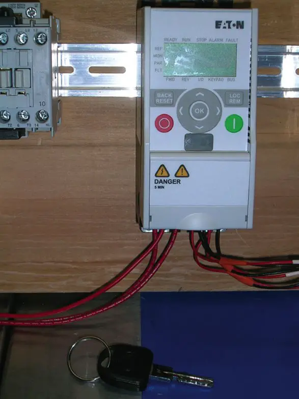
Figure 4 Example of a small variable frequency drive.