The fact that the three waveforms of a three-phase system are 120° apart gives desirable properties to it that makes it attractive from a practical viewpoint.
The very first property of the voltages in the three-phase system is that at each instant of time the sum of all the voltages is zero. This can be mathematically shown, but here we can observe that from the graphics in Figure 1 for only a few points.
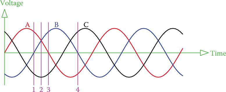
Figure 1 The sum of the voltages of the three phases are always zero.
At any instant, such as those marked by lines 1, 2, 3, and 4, one can verify by measurement on the figure that the sum of the values of the voltages of the three phases is zero.
For example, at the instant denoted by line 1, the value of phase B is zero and the other two phases A and C have equal values but with opposite signs (A is positive and C is negative). This is true for any other instant of time.
If the voltages of the three phases are denoted by VA, VB, and VC, then
$\begin{matrix} {{V}_{A}}+{{V}_{B}}+{{V}_{C}}=0 & {} & \left( 1 \right) \\\end{matrix}$
The above fact leads to another way that the three voltage sources in a three-phase system can be connected together. This is shown in Figure 2.
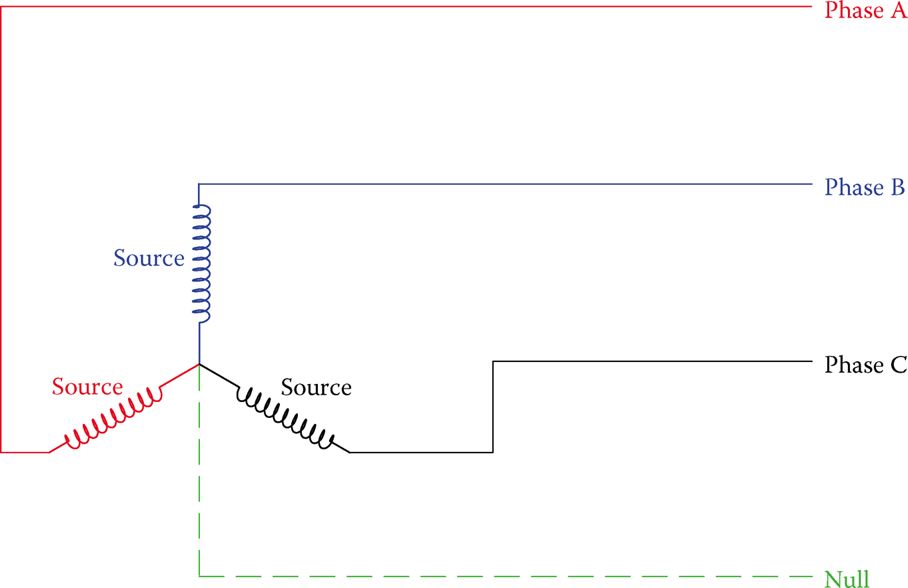
Figure 2 Alternative connection method in three-phase electricity.
In this connection, one end of the three windings are connected together, and the voltage is taken from the other end. The common end can be used as a zero voltage reference point. This point is usually grounded, but there may also be a connection to this point, which is termed a neutral line or null line. The neutral line goes to a similar point on the generation side.
Neutral line: The fourth line in a three-phase system, which ideally does not carry current and can be grounded; also called the null line.
Null line: Same as a neutral line in a three-phase system.
In a three-phase AC system at any instance, the sum of the voltages in the three lines is zero. This is because these voltages are not in phase with each other.
Wye Connection and Delta Connection
The former method of connecting the source voltages together is called a delta connection (or δ connection) because a δ is formed. The latter form of connection is called Y connection (wye connection) or star connection. Note that in delta connection there are only three wires (there is no place for a fourth wire, but in Y-connection one can use three or four wires. The dashed (null) line in Figure 2 can be replaced by a short ground wire, which connects the common point to ground. It is also common practice to carry this wire while also grounding it, all depending on the case, as will be discussed in this chapter.
Delta connection: Way of connecting loads and sources to a three-phase system, where the components of a load or a source form a triangle (or delta, δ) each corner of which is connected to the three lines.
Wye connection: A way of connecting loads and sources to a three-phase system, where the components of a load or a source form a letter Y (that is one side of each component are tied together) and the free sides of the Y are connected to the three lines.
Star connection: Same as wye connection. One of the two ways for connection of loads and sources in a three-phase system.
Note the difference between the voltages in the two cases. At this time the connection to the source is in focus. In a delta connection, the voltage generated in the generator winding is between each of the two lines, whereas in the wye connection the voltage between each line and the null line is equal to that generated in the winding.
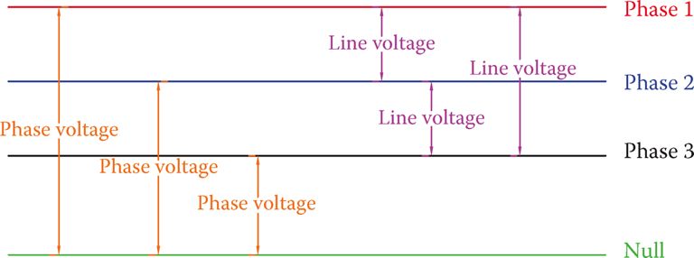
Figure 3 Definition of line voltage and phase voltage.
To distinguish the difference, the terms line voltage and phase voltage are employed. These definitions are depicted in Figure 3.
When there are three lines carrying three-phase electricity, the voltage between every two lines is called line-to-line or simply line voltage.
In the presence of a fourth line, the voltage between each line and the common point (or the null line) is called phase voltage. This is irrespective of how the connection is at the source.
Line voltage: Voltage between each pair of (three) lines bringing electricity to the loads in a three-phase system.
Phase voltage: Voltage between each line and the common reference point (neutral, which is normally grounded) in a three-phase system.
Voltage Relationships in Three-Phase System
Another property of three-phase electricity is the relationship between line voltage and phase voltage. Unless the voltages are disturbed by various load conditions, line voltages for all three phases are the same. Also, all the three phases have the same phase voltages.
Similar to the single-phase electricity, line voltage, and phase voltage express the effective values of the voltages unless mentioned otherwise. If line voltage is denoted by VL and the phase voltage is represented by VP, then
$\begin{matrix} {{V}_{L}}=\sqrt{3}{{V}_{P}} & {} & \left( 2 \right) \\\end{matrix}$
Line and Phase Voltage Calculation Example 1
The voltage across each winding of a generator when working is 120 V. Find the line voltage and the phase voltage for the circuit connected to this generator (1) when the generator windings are delta connected and (2) when the windings are wye connected.
Solution
- Delta connection: Because the voltage across each winding is 120 V, then the line voltage is 120 V. The phase voltage thus can be found from Equation 2 as
\[{{V}_{P}}=\frac{{{V}_{L}}}{\sqrt{3}}=\frac{120}{1.73}=69.28V\]
- Y connection: In this case for each phase, the voltage between the two ends of its winding is 120 V. Thus, the phase voltage is 120 V.
The line voltage is determined from Equation 2 as
${{V}_{L}}=\sqrt{3}{{V}_{P}}=1.732*120=207.85V$
Note that, as this example shows, depending on how the wires are connected together at the source, the voltages can be different. This becomes very important when connecting a source and a load to a circuit.
Often, the windings in a load are not initially connected. There are six terminals for either a three-phase source or a three-phase load (two terminals for the two ends of each winding). A technician must connect these together in the correct way for the desired connection.
- You May Also Read: Three-Phase Electricity Explained
In expressing the voltage in three-phase electricity, in order to make it clear that nobody doubts whether the given value is for the line voltage or the phase voltage, it is common to state both values. This is particularly done for standard voltage values. For example, in expressions like 120/208 V line and 220/380 line, there is no doubt that the larger value is for the line voltage.
A three-phase source or load has six terminals. They must be connected together in the correct way to form a delta connection, or wye connection, as desired.