| 1. | The minimal electrical circuit must contain three parts-a source, a path and a:
|
| 2. | The source of supply of an electrical circuit is:
|
| 3. | The load of an electrical circuit is the part that:
|
| 4. | An electrical circuit needs a conductor to:
|
| 5. | Switches control current flow within a circuit. When a circuit is open:
|
| 6. | Look at the following diagram: 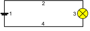 With reference to the simple circuit shown above, the element marked ‘3’ is the:
|
| 7. | For ammeters to read the current in a circuit, the ammeter must be connected so that:
|
| 8. | In a series-connected circuit, there is only one path and the current from the source:
|
| 9. | Look at the following diagram: 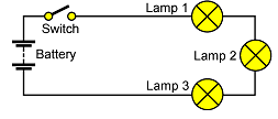 The above drawing shows a:
|
| 10. | In a parallel-connected circuit:
|
| 11. | Look at the following diagram: 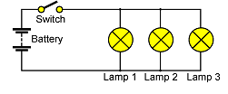 In the diagram, the loads are connected:
|
| 12. | Compound circuits are made up of:
|
| 13. | Look at the following diagram: 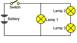 In the above diagram, the lamps are connected as a:
|
| 14. | Look at the following diagram: 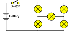 The above diagram represents a:
|
| 15. | When resistors are connected together, they can be replaced by a single resistor with the same overall resistance as the set of resistors. A resistor that has the same value as a group of combined resistors is called:
|
| 16. | Loops are an engineering title for what electricians would normally refer to as:
|
| 17. | Look at the following diagram: 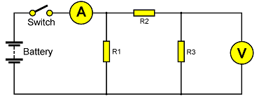 The number of current loops in the above circuit is:
|
| 18. | The common electrical abbreviation for the potential difference between two points is:
|
| 19. | Look at the following diagram:  With reference to the memory jogger called ‘Ohm’s Triangle’ shown above, if the value of the current in a given circuit is required it can be determined by:
|
| 20. | Look at the following diagram: 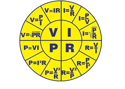 This diagram shows the power wheel which can be used as a memory jogger when solving simple circuit analysis problems. This wheel is derived from:
|
| 21. | Kirchhoff’s Voltage Law states that in any given circuit, the algebraic sum of the applied EMFs is equal to the:
|
| 22. | The following formula can be used to determine the total resistance in a series circuit. In the formula the symbol R1 stands for the:
|
| 23. | Look at the following diagram: 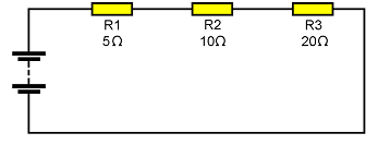 The equivalent resistance to replace the three resistors in the series circuit shown above is:
|
| 24. | The equivalent resistance of a number of series resistors is always:
|
| 25. | When a number of components are in series, the current must pass through each component to return to the source. Therefore, should any one component, conductor or joint become an open circuit, the current:
|
| 26. | The voltage across any number of components connected in parallel will:
|
| 27. | Kirchhoff’s Current Law states that the sum of the currents entering a junction:
|
| 28. | The following formula can be used to determine the equivalent resistance of a number of resistors in parallel: In the formula the symbol ‘RTotal‘ stands for the:
|
| 29. | Look at the following diagram: 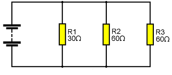 The equivalent resistance to replace the three resistors in the parallel circuit shown above is:
|
| 30. | The equivalent resistance of a number of parallel resistors is always:
|
| 31. | In a parallel circuit, if one branch becomes open circuit, the:
|
| 32. | When identifying sections of a compound circuit, components that are joined by a single conductor with no other connections, are connected in:
|
| 33. | When simplifying compound circuits by the equivalent resistance method, wherever two or more resistors are found to be in series, they may be simplified by:
|
| 34. | One method that can be used to find the total power in a circuit is to find the individual power used in every component and then:
|
| 35. | Look at the following diagram:  The diagram shown above has a battery of four 1.5 volt cells, connected via a switch to a 3 watt lamp. When the switch is closed, the current drawn from the battery will be:
|
| 36. | Look at the following diagram:  The reading on the ammeter in the above circuit will be:
|
| 37. | Look at the following diagram: 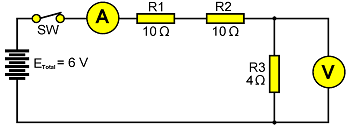 The reading on the voltmeter in the above circuit will be:
|
| 38. | Parallel circuits have:
|
| 39. | Look at the following diagram: 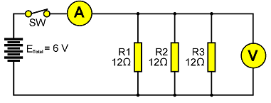 The equivalent resistance of the above circuit is:
|
| 40. | Look at the following diagram: 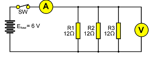 With reference to the above circuit, the reading on the ammeter will be:
|
| 41. | Look at the following diagram: 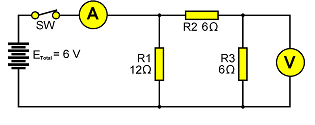 With reference to the above circuit, the current through resistor ‘R1’ will be:
|
| 42. | Look at the following diagram: 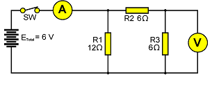 With reference to the above circuit, the reading on the ammeter will be:
|
| 43. | Look at the following diagram:  With reference to the above circuit, the reading on the voltmeter will be:
|