Magnetism and Electromagnetism MCQs with Answers

1. Look at the following diagram:    
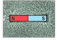
The above diagram shows the magnetic field produced by a bar magnet. As they expand away from the magnet the magnetic fields: 
 

A.  become weaker
B.  gain extra strength
C.  begin to alternate
D.  change polarity


2. By convention a magnetic lines of force are considered to: 
 

A.  acts outwards from the south-pole of a magnet and inwards at the north-pole
B.  acts outwards from the north-pole of a magnet and inwards at the south-pole
C.  acts outwards from the north-pole of a magnet and inwards at the north-pole
D.  acts outwards from the south-pole of a magnet and inwards at the south-pole


3. Magnetic lines of force take the shortest possible path between the north and south poles of a magnet. However, when a material that can be magnetised is placed within the magnetic field, the field is distorted because a: 
 

A.  magnetic material offers no opposition to the magnetic field
B.  magnetic material offers more opposition to the field than a non-magnetic material
C.  magnetic material offers less opposition to the field than a non-magnetic material
D.  magnetic line of force cannot pass through a magnetic material


4. Two magnetic fields acting in the same direction will: 
 

A.  attract one another
B.  cancel one another out
C.  change polarities with one another
D.  repel one another


5. For a ferromagnetic material, the critical temperature above which the dipoles within the material become easy to realign is called the: 
 

A.  Curie point
B.  Saturation point
C.  Magnetic point
D.  Ferro point


6. When a magnet is attracted to a piece of magnetic material, the magnetic field passes through the material, turning it into a temporary magnet. This action is called: 
 

A.  electromotive induction
B.  magnetic induction
C.  magnetic polarisation
D.  ferromagnetic alignment


7. The three most important magnetic materials are iron, nickel and: 
 

A.  copper
B.  silver
C.  cobalt
D.  aluminium


8. One alloy that has made into permanent magnets with superior properties; is Alnico. This alloy consists mainly of: 
 

A.  silver, nickel and cobalt
B.  aluminium, nickel and copper
C.  aluminium, nitrates and cobalt
D.  aluminium, nickel and cobalt


9. Ferromagnetic materials which are easily magnetised are called: 
 

A.  magnetically soft
B.  magnetically hard
C.  mechanically soft
D.  physically hard


10. When the magnetising force is removed from a magnetically soft material, the material tends to demagnetise itself. Any magnetism that remains is called: 
 

A.  coercive magnetism
B.  residual magnetism
C.  electro-magnetism
D.  permeability magnetism


11. Ferrite magnetic materials are manufactured: 
 

A.  from ferromagnetic iron and steel products
B.  at very low temperatures using non-ferromagnetic materials
C.  using a mixture of powdered magnetic materials and a ceramic binder
D.  by a process of electroferro magnetisation


12. Rare earth magnets make the strongest magnets currently available. One common application of these magnets is: 
 

A.  the magnetic field for rechargeable batteries
B.  sintered ferrite cores in electric motors
C.  Curie point temporary magnets for portable tools
D.  electric motor fields for permanent magnet motors


13. When a device needs to be protected from a magnetic field, a magnetic shield is used. Magnetic shields divert the magnetic field by: 
 

A.  providing a path of much greater permeability
B.  acting as a magnetic insulator
C.  blocking the magnetic field in all directions
D.  acting as a very low permeability bypass


14. Look at the following diagram:    
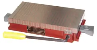
The above drawing shows a magnetic chuck which uses the holding power of magnets to retain magnetic materials firmly in position on the worktable of a machine during machining processes. One important advantage of the magnetic chuck is that: 
 

A.  the event of an electrical failure, the material will be released
B.  no electrical connections are needed
C.  magnetic materials are free to move during the process
D.  they are much less expensive than four-jaw chucks


15. When current travels along a conductor, a magnetic field surrounds the conductor. This magnetic field: 
 

A.  increases if the current decreases
B.  decreases if the current increases
C.  increases if the current increases
D.  is constant for values of current


16. Electromagnets can replace permanent magnets in most applications, with the added advantage that electromagnets: 
 

A.  are made from rare-earth materials
B.  do not need to have a south pole
C.  are permanently in the magnetised state
D.  can be varied in magnetic strength


17. The right-hand grip rule for straight conductors states that if the imaginary conductor is gripped with the thumb pointing in the direction of the current flow, then the fingers point in the direction of the: 
 

A.  magnetic field
B.  electron flow
C.  resistance effect
D.  supply voltage


18. Look at the following diagram:    
Using the right-hand grip rule for a straight conductor, the direction of the magnetic field in the above diagram will be: 
 

A.  clockwise
B.  anti-clockwise
C.  vertically upwards
D.  vertically downwards


19. Look at the following diagram:    
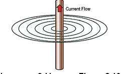
With reference to the above diagram, the strength of the magnetic field around a straight conductor depends on the value of the current in the conductor. Doubling the current results in: 
 

A.  no change to the strength of the magnetic field
B.  a change of direction in the magnetic field
C.  double the strength of the magnetic field
D.  the magnetic field beginning to alternate


20. Look at the following diagram:    
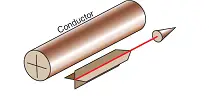
The above diagram illustrates the convention for indicating the direction of current flow in a conductor. The ¤ symbol indicates the current is flowing: 
 

A.  from North to South
B.  from South to North
C.  away from the observer
D.  towards the observer


21. By winding a conductor into a coil of many turns, the magnetic field strength is: 
 

A.  increased in proportion to the number of turns in the coil
B.  decreased in proportion to the number of turns in the coil
C.  increased in inverse proportion to the number of turns in the coil
D.  increased in proportion to magnetic field strength of the wire


22. The direction of the magnetic field generated by a solenoid can be determined using the right-hand grip rule. This rule states that when the right hand is placed over a solenoid coil so that the fingers point in the direction of the current flow, the thumb points in the direction of the: 
 

A.  South pole of the magnetic field
B.  North pole of the of the magnetic field
C.  current through the solenoid
D.  power generated by the current flow


23. Look at the following diagram:    
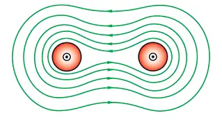
The above diagram shows the magnetic forces between two conductors carrying current in the same direction. This force causes the conductors to: 
 

A.  rotate clockwise
B.  rotate anticlockwise
C.  be attracted towards one another
D.  be repelled by one another


24. Therefore, the magnetic force between two conductors with a known current flow in each conductor and with a known distance separating the conductors can be calculated from the formula: 
 

A.  F = 4E – 7 x I1I2 x s
B.  F = 2E – 8 x I1I2/s
C.  F = 2E – 7 x V1I1/s
D.  F = 2E – 7 x I1I2/s


25. Two long parallel conductors 0.015 m apart each carry a current of 200 A in opposite directions. The force between them will be: 
 

A.  0.53 Newtons
B.  0.053 Newtons
C.  0.026 Newtons
D.  2.60 Newtons


26. The force required to create a magnetic field is called the: 
 

A.  electromotive force
B.  magnetomotive force
C.  electrostatic force
D.  magnodynamic forcer


27. The magnetic field strength of a coil is proportional to the product of the: 
 

A.  north and south poles of the coil
B.  current and the length of the coil
C.  current and the number of turns in the coil
D.  supply voltage and the number of turns in the coil


28. The following formula can be used to determine the magnetomotive force in a magnetic circuit:
Fm = IN
In the formula the symbol ‘N’ stands for the: 
 

A.  current flowing in amperes
B.  number of magnetic poles in the circuit
C.  magnetising node strength number
D.  number of turns in coil


29. A current of 7 A flows in a coil of 100 turns, the value of MMF creating a magnetic flux is: 
 

A.  700 At
B.  170 At
C.  107 At
D.  14.28 At


30. The magnetising force for a portion of a magnetic circuit is the MMF required to magnetise a unit length of a magnetic path and is expressed in: 
 

A.  ampere-turns per Henry
B.  ampere-turns per metre
C.  amperes per applied volts
D.  Webers per metre


31. The flux density of a magnetic circuit is measured in: 
 

A.  volts per metre
B.  ampere turns per volt
C.  webers per square metre
D.  teslas per square metre


32. The flux density of a magnetic path can be found from the formula:    
In the formula the symbol Φ stands for: 
 

A.  cross-sectional area of the magnetic circuit
B.  change in current in amperes
C.  flux density in teslas per square metre
D.  total magnetic flux in webers


33. A magnetic circuit has a cross-sectional area of 100 mm2 and a flux density of 0.015T. The total flux in the circuit will be: 
 

A.  1.5 E-6 Wb
B.  2.5 E-6 Wb
C.  0.15 E-6 Wb
D.  100 E-6 Wb


34. A conductor carrying a current within a magnetic field will have: 
 

A.  no opposition to current flow
B.  a force placed upon it
C.  no magnetic field around it
D.  one induced tesla per metre


35. The value of the force on a conductor within a magnetic flux can be found from the formula,    
In the formula, the symbol B stands for: 
 

A.  current in amperes
B.  length of the conductor in metre
C.  flux density in teslas
D.  flux density in webers


36. A conductor has been placed at right angles to a magnetic field with a flux density of 0.5 T over a length of 0.15 m of the conductor. If the current through the conductor is 15 A, then force exerted on the conductor will be: 
 

A.  15.65 N
B.  11.25 N
C.  1.565 N
D.  1.125 N


37. The permeability of a magnetic material is defined as the: 
 

A.  ease with which a magnetic flux can be created in that material
B.  opposition to a magnetic flux being created in that material
C.  amount of permanent magnetism left when the current stops
D.  ability of a magnetic material to become a permanent magnet


38. The permeability of free space (a vacuum), is equal to: 
 

A.  2πE – 7
B.  4πE – 7
C.  4πE – 8
D.  2πE – 8


39. To find the actual permeability of a material, the following formula can be used:    
In the formula, the symbol μr is used for the: 
 

A.  actual permeability of the material
B.  permeability of the material in a vacuum
C.  relative permeability of the material
D.  permeability of free space


40. The term used to describe the opposition by a material to being magnetised is: 
 

A.  magnetic permeability
B.  magnetic acceptance
C.  magnetomotive flux ratio
D.  magnetic reluctance


41. The reluctance of a magnetic circuit depends on a number of factors. These are the length, the cross sectional area and the: 
 

A.  permeability of the circuit material
B.  distance around the circuit material
C.  electrical current through the circuit material
D.  number of North and South poles in the magnetic circuit


42. The reluctance of a magnetic circuit can be found using the formula shown below.    
In the formula the symbol ‘A’ stands for the: 
 

A.  current in amperes in the electrical circuit
B.  cross-sectional area of the magnetic circuit
C.  absolute value of the magnetic permeability
D.  length of the magnetic circuit in metres


43. An iron core has a total mean length of magnetic path of 250 mm. The core is rectangular in cross-section with dimensions 15 mm x 15 mm. The core has a relative permeability of 800 at the designed flux density. The reluctance of the core will be: 
 

A.  1.105 E4 AT/Wb
B.  1.268 E6 AT/Wb
C.  1.105 E6 AT/Wb
D.  884.1 E6 AT/Wb


44. The equivalent of Ohm’s Law for magnetic circuits is stated as:    
In the formula the term IN represents the: 
 

A.  magnetic flux in the magnetic circuit in webers
B.  reluctance of the circuit in ampere turns per weber
C.  electromotive force in amperes2 per tesla
D.  magnetomotive force in ampere-turns


45. An electromagnet has 500 turns and the total reluctance of the magnetic core is 750 IN/Wb. The flux produced when 12 A flows through the coil will be: 
 

A.  8 Wb
B.  12.8 Wb
C.  6000 Wb
D.  9000 Wb


46. A contactor coil has 7000 turns and draws 0.12 A from the supply. When energised the total flux produced by the coil is 700 E-6 Wb. The magnetic reluctance of this circuit is: 
 

A.  7.2 E-6 AT/Wb
B.  1.2 E-6 AT/Wb
C.  72 E-6 AT/Wb
D.  12 E-6 AT/Wb


47. With reference to the magnetising characteristic of non-magnetic materials, the flux density ‘B’ varies directly with magnetising force ‘H’. Therefore the graph of ‘B’ against ‘H’ will be: 
 

A.  in the shape of a parabola
B.  exponential
C.  a straight line
D.  in the shape of a peak


48. B/H curves are commonly used as a means of comparing the: 
 

A.  voltage of a battery against a magnetic circuit
B.  magnetising force against the relative permeability of a magnetic material
C.  ampere turns of a magnetic circuit against the magnetising force
D.  magnetic characteristics of different types of magnetic materials


49. Look at the following graph:    
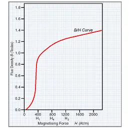
The B/H curve in the diagram above shows that when the value of H is low, small increases in the value of the magnetising force (H) will produce: 
 

A.  large increases in the value of the flux density
B.  small increases in the value of the flux density
C.  no increases in the value of the flux density
D.  saturated increases in the value of the flux density


50. With reference to the drawing shown above in QUESTION 49, as the magnetising force increases towards 2000 AT/m, the flux density increases less and less. This indicates that magnetic saturation is taking place. Saturation is said to occur at a flux density near the: 
 

A.  bottom of the B/H curve
B.  centre of the knee of the B/H curve
C.  middle of the vertical section of the B/H curve
D.  ankle of the B/H curve


51. Look at the following graph:    
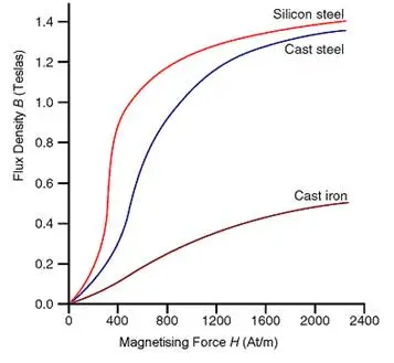
The graph illustrates the magnetisation curves for silicon steel, cast steel and cast iron. The curves show that silicon steel saturates at a: 
 

A.  slightly higher value of flux density than cast steel
B.  slightly lower value of flux density than cast iron
C.  slightly lower value of flux density than cast steel
D.  much lower value of flux density than cast steel


52. The graph in QUESTION 51 illustrates the magnetisation curves for silicon steel, cast steel and cast iron. The curves show that cast iron is: 
 

A.  much easier to magnetise than silicon steel
B.  much easier to magnetise than cast steel
C.  much harder to magnetise than cast iron
D.  much harder to magnetise than silicon steel


53. In electrical terminology term ‘hysteresis’ is used to describe the lag between a change in value or direction of the magnetising force and the: 
 

A.  resulting change in value or direction of flux
B.  resulting change in the value of the magnetising force
C.  change in the value of coercive force required
D.  change in the value of residual force required for flux


54. Even after the magnetising force is removed, some magnetism remains. This is known as: 
 

A.  hysteresis magnetic flux
B.  residual magnetism
C.  latent magnetising force
D.  coercive flux


55. The force that is used to remove residual magnetism is known as the: 
 

A.  residual force
B.  magnetising force
C.  coercive force
D.  hysteresis force


56. Look at the following graph:    
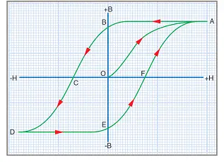
The graph represents the hysteresis loop of the magnetising force plotted against the flux density in both directions. On the graph, OB and OE indicate the values of: 
 

A.  magnetising force at maximum flux density
B.  flux density at minimum magnetising force
C.  residual magnetising force at zero flux density
D.  residual flux density at zero magnetising force


57. Reversing the magnetic field within the magnetic material results in the: 
 

A.  generation of heat within the material
B.  flux density increasing
C.  the material reversing its direction
D.  temperature of the material lowering


58. Look at the following graph:    
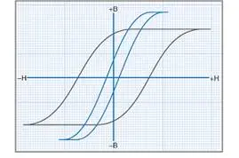
The graph compares the hysteresis loops of transformer steel and carbon steel. The hysteresis loop with the comparatively small area: 
 

A.  has greater losses than the other
B.  is for transformer steel
C.  indicates that carbon steel has less hysteresis losses
D.  requires a greater magnetising force


59. Look at the following diagram:    
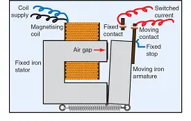
With reference to the magnetic circuit shown above, the total magnetic flux does not reach the air gap, but leaves the iron poles and passes through the surrounding air. The flux which leaves the main path is known as: 
 

A.  the magnetomotive force
B.  negative magnetic flux
C.  the leakage flux
D.  magnetising coil flux


60. Look at the following diagram:    
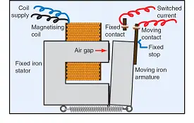
The above drawing shows a simple attracted-armature type of relay. When current flows in the operating coil, a magnetic flux is created: 
 

A.  between the moving contacts of the external circuit
B.  in the fixed contact of the external circuit
C.  only in the air gap only between the armature and core
D.  in the soft iron core and around the magnetic circuit


61. Some electrical machines are prone to failure when the supply voltage is lower than the value that the machine was designed for. No-volt relays, low-volt relays or brown-out relays, have an operating coil connected across the supply voltage. In these relays, the armature and contacts close when the: 
 

A.  supply is energised
B.  supply is de-energised
C.  supply voltage is very low
D.  supply is DC only


62. The operating coil of an overload relay is connected: 
 

A.  in parallel with the current flowing in the circuit
B.  in series with the current flowing in the circuit
C.  so that the supply voltage appears across the coil
D.  so that it reads the minimum current flow in the circuit


63. Polarised relays operate only when: 
 

A.  an AC supply is applied
B.  the relay is connected to an alternating supply
C.  the polarity of a DC supply is correct
D.  the magnetic circuit has two North di-poles