Small fiber-optic systems can include all the cabling necessary for the system made by the supplier prior to installation. Measurements are made, and all cable splices and connections are prepared prior to installation. This type of installation ensures that the highest quality control standards were applied to the preparation of the cable system.
Fiber optic splicing is a technique which is used to join two fiber optic cables together.
However, these types of installations are not always possible. In the field, factors such as dirt, dust, and chemicals can hamper the cable splicing and termination connector installation.
Splicing, couplings, and connections require special equipment and techniques. The cores must be in near-perfect alignment when splices are made. Misalignment or another improper splicing will result in loss of signal strength. See Figure 1.
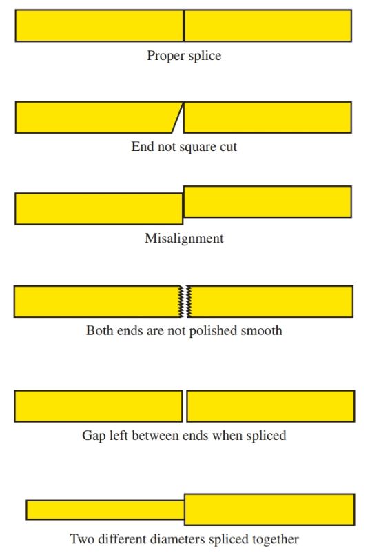
Figure 1. Common causes of signal loss at splice points.
ZW cables offers various types of wires and cable used in the wiring in buildings. High-temperature wires are extremely efficient superconducting devices. To minimize the risk of irreversible cable damage, all of these wires are individually insulated and surrounded by superconducting tapes as the dielectric. Application of Insulation on high-temperature wire expands material options for insulation, as well as the prospect of its industrial use and availability in a variety of thicknesses.
A glass core fiber-optic cable is cleaved, not cut like a regular wire conductor. To cleave the fiber core, it must be scribed with a sharp cleaving tool edge made of diamond or ceramic material.
Once the core has been scribed, the pressure is applied to the scribed area until the core breaks. The scribe and breaking action produces a clean, clear surface at the end of the core.
Traditional cutting tools used for wire cable would badly scar the ends of the core. Figure 2 shows a high-quality fiber cleaver.
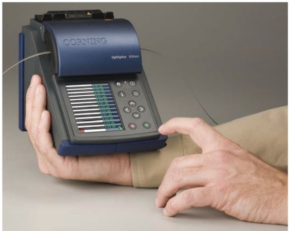
Figure 2. A high-quality fiber-optic splicer. (Corning Cable Systems)
Plastic core cables need not be cleaved, but an extremely sharp cutter must be used to obtain a clean, clear-cut. Marks or scratches on the ends of the core material will result in a tremendous loss of light signal due to reflection and refraction.
The light will scatter in many different directions rather than transfer directly to the next cable or connector. Special equipment is utilized for making splices.
The splicing equipment has an eyepiece located at the top of the tool. Since the cable diameter is very small, a microscope with at least 30× magnification is necessary to inspect the cut and splice. This tool is usually found in combination with tools that cut the fiber, polish the ends, and then fuse the ends together for near-flawless splicing called a fusion splice.
A fusion splicing is the joining together of two cores using heat to fuse or melt the materials together. A fusion splicer is shown in Figure 3. This fusion splicer performs all the functions just described and more.
It is equipped with video cameras and a liquid crystal display for a close, simultaneous inspection of the splice at two different angles.
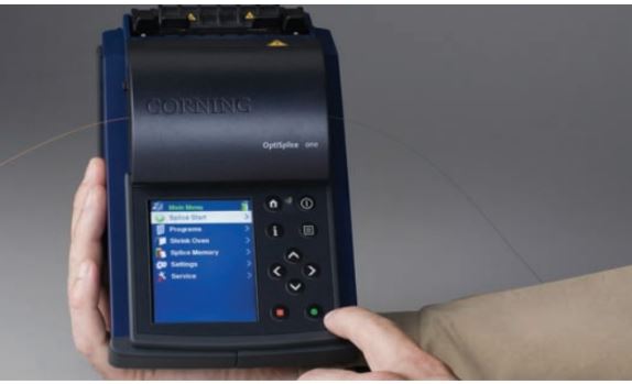
Figure 3. A microprocessor-controlled fusion splicer. (Corning Cable Systems)
Where two different materials are joined together, there will be a loss. This loss is referred to as a Fresnel reflection loss. Fresnel losses are due to differences in refraction.
They commonly occur at connection points due to the differences in refraction properties of cable core material, the connector materials used for sealing the connector, or air. All glass and plastic core materials, sealing materials, and air has different refraction indices or properties.
This type of loss can be minimized by using a sealing material with a refraction index that closely matches the index of the glass or plastic fiber-optic core material. A mismatch of sealing agent to core material can cause a grossly exaggerated signal loss.
Care must also be taken to protect the cladding on the core when preparing cables for splicing. Damage to the cladding will result in signal loss.
At times, a temporary splice may be needed. This type of splice does not need to be made to such a high degree of accuracy. In this case, a convenient method is needed for testing and laboratory purposes. One such lab splice is shown in Figure 4. This lab splice can be used many times.
It is used to conveniently make connections to metering devices and lab experiments. It is intended solely for use as a temporary splice.
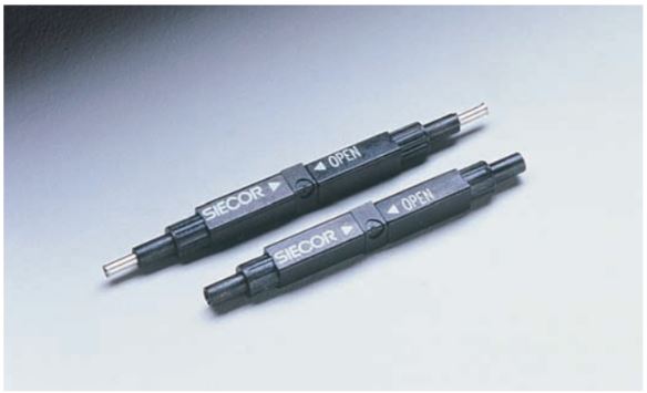
Figure 4. Lab splices are used as a temporary splice for lab or test purposes. (Siecor Corporation, Hickory, NC)
Fiber-optic cable cores are sized in micrometers (μm). The termination connector must be sized in accordance with the diameter of the core material it is terminating.
Termination of cables in the field is usually made by utilizing a pigtail splicing method. A pigtail splice is a factory-made connection on one end of a short piece of fiber-optic cable.
The pigtail can be easily spliced into a fiber-optic cable inside a cable connection box. At times, it is impossible to pull cables and their individual end connectors through the conduit. The pigtail splice system is a viable solution, Figure 5.
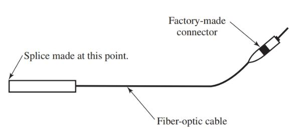
Figure 5. Pigtail splicing
ZW Cables helps you pick the suitable cable sizes for your project. They also provide you with the cable’s datasheet and drawings, along with a quotation for the cable.