Key components of a power supply include transformers, rectifiers, filters, voltage regulators, and protection circuits. Understanding the functions and components of power supplies is crucial for designing and operating electronic systems effectively.
What is a Power Supply?
A power supply is an electronic circuit designed to provide various ac and dc voltages for equipment operation.
Proper operation of electronic equipment requires a number of source voltages. Low dc voltages are needed to operate ICs and transistors. High voltages are needed to operate CRTs and other devices. Batteries can provide all of these voltages.
However, electricity for electrical and electronic devices are commonly supplied by the local power company. This power comes out of an outlet at 115-volt ac, with a frequency of 60 Hertz. Different voltages are needed to operate some equipment.
Power Supply Functions
The complete power supply circuit can perform these functions:
- Step voltages up or step voltages down, by transformer action, to the required ac line voltage.
- Provide some method of voltage division to meet equipment needs.
- Change ac voltage to pulsating dc voltage by either half-wave or full-wave rectification.
- Filter pulsating dc voltage to a pure dc steady voltage for equipment use.
- Regulate power supply output in proportion to the applied load.
Power Supply Components
A block diagram illustrating these functions is shown in Figure 1. Note that certain functions are not found in every power supply. See Figure 2 for a typical commercial power supply components.
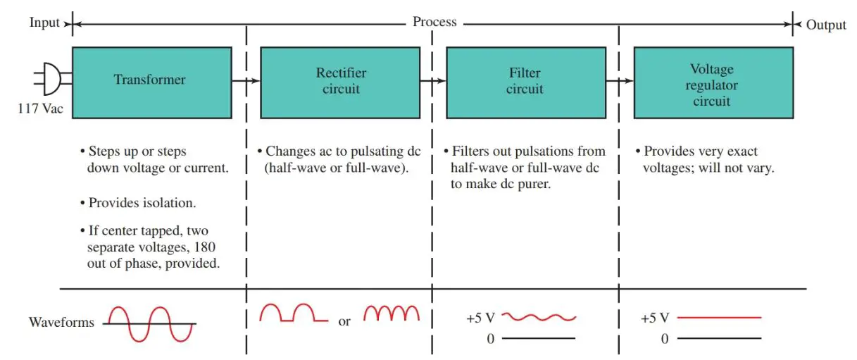
Figure 1. Block diagram for power supply components. Input is 117 volts ac. Processes used in a typical power supply are shown below the blocks. The output of the power supply can be dc or ac. The output of this supply is five volts dc.
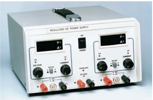
Figure 2. Regulated dc power supply. (Knight Electronics)
Power Supply Transformers
The first device in a power supply is the transformer. Its purpose is to step up or step down alternating source voltage to values needed for radio, TV, computer, or other electronic circuit use.
Most transformers do not have any electrical connection between the secondary and primary windings. See Figure 3. This means that the transformer isolates the circuit connected to the primary from the circuit connected in the secondary.
Isolation is a term that means there are no electrical connections between the primary and secondary on the transformer.
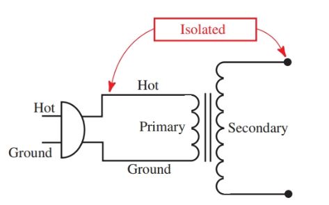
Figure 3. Isolation in a transformer.
An isolation transformer is a transformer that has the specific purpose of isolating the primary circuit from the secondary circuit.
Using an isolation transformer is a safety feature because it helps prevent shocks in the secondary. Our body or hands must be joined across both leads of the secondary connections in order to receive a shock.
The safety condition described above does not hold true in the primary with commercial ac provided by the power company. One connection is hot, which means that the connection is electrically energized. The other is grounded, or neutral. Standing on the ground while touching the hot connection will result in a shock. Touching the ground connection alone will not result in a shock.
Secondary windings can be tapped to provide different voltages. A tap placed midway between the two ends of a secondary winding is called a center tap.
Many power supplies use a center tap secondary transformer winding. The tapped voltages, Figure 4, are 180 degrees out of phase with respect to the center tap.
A variety of transformers can be found in nearly all electronic devices. You should understand the basic theory and purpose of the transformer. Review Chapter 12 if necessary.
A Lesson in Safety
Transformers produce high voltages that can be very dangerous. Proper respect and extreme caution must be used at all times when working with, or measuring, high voltages.
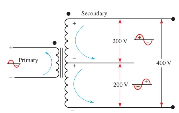
Figure 4. A center tap transformer.
How Does a Power Supply Convert AC To DC?
After a voltage has gone through a power supply’s transformer, the next step is rectification.
The process of changing an alternating current to a pulsating direct current is called rectification.
When changing an ac signal to dc, there are two types of rectification: half-wave rectification and full-wave rectification.
With the half-wave rectifier, only half of the input signal passes on through the rectifier. With the full-wave rectifier, the entire input wave is passed through.
Half-Wave Rectification
In Figure 5, the output of a transformer is connected to a diode and a load resistor that are in series. The input voltage to the transformer appears as a sine wave.
The polarity of the wave reverses at the frequency of the applied voltage. The output voltage of the transformer secondary also appears as a sine wave. The magnitude of the wave depends on the turns ratio of the transformer. The output is 180 degrees out of phase with the primary.
The top of the transformer (point A) is joined to the diode anode. Note that the B side of the transformer is connected to ground.
During the first half cycle, point A is positive. The diode conducts, producing a voltage drop across resistor R equal to IR. During the second half cycle, point A is negative. The diode anode is also negative. No conduction takes place, and no IR drop appears across R.
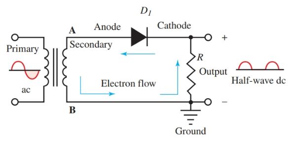
Figure 5. Basic diode rectifier schematic.
An oscilloscope connected across R produces the waveform shown to the right in Figure 6. The output of this circuit consists of pulses of current flowing in only one direction and is at the same frequency as the input voltage. The output is a pulsating direct current.
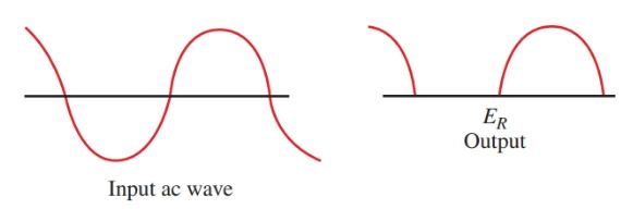
Figure 6. Input and output waveforms of a diode rectifier.
Only one half of the ac input wave is used to produce the output voltage. This type of rectifier is called a half-wave rectifier.
Look at the polarity of the output voltage in Figure 6. One end of the resistor R is connected to ground. The current flows from the ground to the cathode. This connection makes the end of R connected to the cathode positive as shown in Figure 5.
A negative rectifier can be made by reversing the diode in the circuit, Figure 7. The diode conducts when the cathode becomes negative causing the anode to become positive.
The current through R would be from the anode to ground making the anode end of R negative and the ground end of R more positive.
Voltages taken from across R, the output, would be negative with respect to ground. This circuit is called an inverted diode. It is used when a negative supply voltage is required.
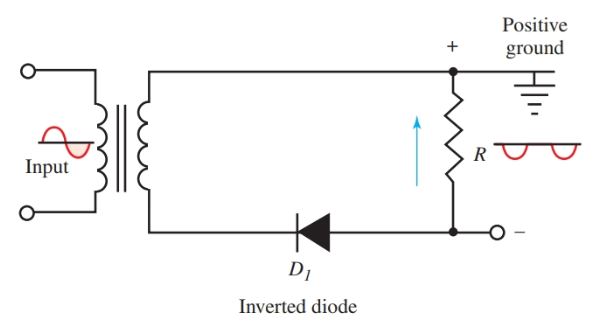
Figure 7. An inverted diode produces a negative voltage.
It is possible to have a power supply that provides half-wave rectification without the use of a transformer. This circuit is not isolated. There is no step up or step down of current voltages. This circuit is a simpler, less costly design, and since there is no transformer, it can be used in smaller spaces, Figure 8.

Figure 8. Half-wave rectification without a transformer.
Full-Wave Rectification
The pulsating direct voltage output of a half-wave rectifier can be filtered to a pure dc voltage. However, the half-wave rectifier uses only one half of the input ac wave.
A better filtering action can be obtained by using two diodes. With this setup, both half cycles of the input wave can be used.
Both half cycles at the output have the same polarity in this full-wave rectifier. Figure 9 follows the first half cycle. Figure 10 follows the second half cycle.
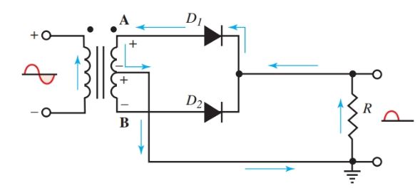
Figure 9. Arrows show current in full-wave rectifier during the first half cycle.
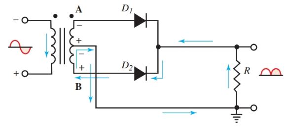
Figure 10. The direction of current during the second half cycle.
To produce this full-wave rectification, a center tap is made on the secondary winding. This tap is attached to the ground.
In Figure 9, point A is positive and diode anode D1 is positive. Electron flow is shown by the arrows. During the second half of the input cycle, point B is positive, diode anode D2 is positive, and current flows as shown in Figure 10.
No matter which diode is conducting, the current through load resistor R is always in the same direction. Both positive and negative half cycles of the input voltage cause the current through R in the same direction.
The output voltage of this full-wave rectifier is taken from across R. It consists of direct current pulses at twice the frequency of input voltage, Figure 11. To produce this full-wave rectification in this circuit, the secondary voltage was cut in half by the center tap.
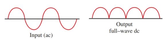
Figure 11. The waveforms of input and output of full-wave diode rectifier.
The diodes, D1 and D2, used in Figures 9 and 10, are packaged both individually and in pairs. Figure 12 shows a two rectifier package. The center lead is used as the connection for the cathodes. The cathodes are wired together.
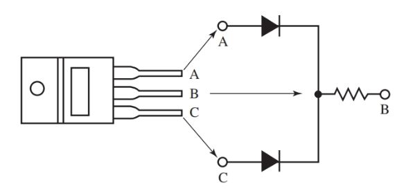
Figure 12. Dual diodes with a center tap.
Bridge Rectifiers
It is not always necessary to use a center-tapped transformer for full-wave rectification. Full secondary voltage can be rectified by using four diodes in a circuit called a bridge rectifier, Figure 13 and 14. Two circuits are shown so that the current can be observed in each half cycle.
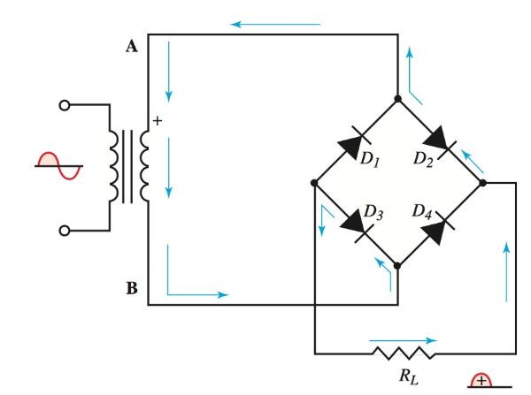
Figure 13. Current in bridge rectifier during the first half cycle.

Figure 14. Current in bridge rectifier during the second half cycle.
In Figure 13, point A of the transformer secondary is positive. Current flows in the direction of the arrows. When point B is positive, current flows as in Figure 14.
Again, notice that the current through R is always in one direction. Both halves of the input voltage are rectified and the full voltage of the transformer is used.
Bridge rectifiers can be used in circuits without transformers. Without transformers, the voltage or current will not be stepped up or down. There will be no isolation. These circuits are also called line-operated bridge circuits, Figure 15.
Caution
Connecting an oscilloscope directly to a line-operated bridge rectifier will result in a dead ground when the oscilloscope ground is connected to the line voltage bridge. An isolation transformer with a 1 to 1 ratio must be used to prevent the ground lead on the scope from being connected to the hot conductor.
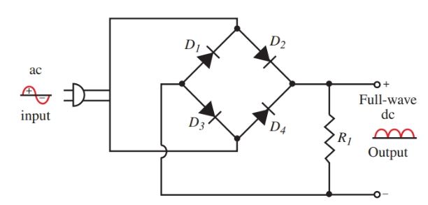
Figure 15. Line-operated bridge rectifier circuit.
The output of either the half-wave or full-wave rectifier is a pulsating voltage. Before it can be applied to other circuits, the pulsations must be reduced. A steadier dc is needed. It can be obtained using a filter network.
In Figure 16, the line, Eavg, shows the average voltage of the pulsating dc wave. It is equal to 0.637 × peak voltage. The shaded portion of the wave above the average line is equal in area to the shaded portion below the line.
Movement above and below the average voltage is called the ac ripple. It is this ripple that requires filtering.
The percentage of ripple as compared to the output voltage must be kept to a small value. The ripple percentage can be found using the formula:
\[Percentage\text{ }Ripple=\frac{{{E}_{rms}}\text{ }of\text{ }Ripple\text{ }Voltage}{{{E}_{avg}}\text{ }of\text{ }Total\text{ }Output\text{ }Voltage}\times 100%\]
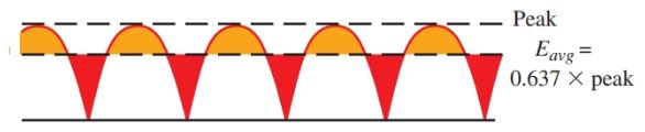
Figure 16. Average value of full-wave rectifier output.
What Is a Capacitor Filter?
A capacitor connected across the rectifier output provides some filtering action, Figure 17. The capacitor is able to store electrons.
When the diode or rectifier is conducting, the capacitor charges rapidly to near the peak voltage of the wave. It is limited only by the resistance of the rectifier and the reactance of the transformer windings.
Between the pulsations in the wave, voltage from the rectifier drops. The capacitor then discharges through the resistance of the load.
The capacitor, in effect, is a storage chamber for electrons. It stores electrons at peak voltage and then supplies electrons to the load when rectifier output is low. See Figure 18.
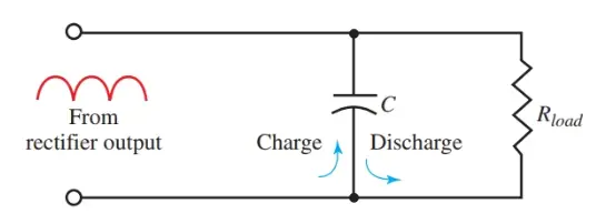
Figure 17. Filtering action of a capacitor.
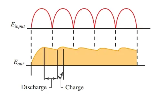
Figure 18. Input and output of the capacitor filter showing the change in the waveform.
Capacitors used for this purpose are electrolytic types because large capacitances are needed in a limited space. Common values for the capacitors range from 4 to 2000 microfarads. Working voltages of capacitors should be in excess of the peak voltage from the rectifier.
What is an LC Filter?
The filtering action can be improved by adding a choke in series with the load. This LC filter circuit appears in Figure 19. The filter choke consists of many turns of wire wound on a laminated iron core.
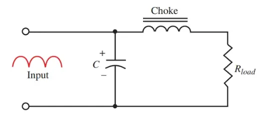
Figure 19. Further filtering is produced by the choke in series with the load.
Recall that inductance was that property of a circuit that resisted a change in current. A rise in current induced a counter emf that opposed the rise. A decrease in current induced a counter emf that opposed the decrease. As a result, the choke constantly opposes any change in current. Yet, it offers very little opposition to a direct current.
Chokes used in radios have values from 8 to 30 henrys. Current ratings range from 50 to 200 milliamperes.
Larger chokes can be used in transmitters and other electronic devices. Filtering action as a result of the filter choke is shown in Figure 20.
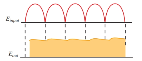
Figure 20. Waveforms show the filtering action of the capacitor and choke together.
A second capacitor can be used in the filter section after the choke, to provide more filter action. See Figure 21. The action of this capacitor is similar to the first capacitor. The circuit configuration appears as the Greek letter π. The filter is called a pi (π) section filter.
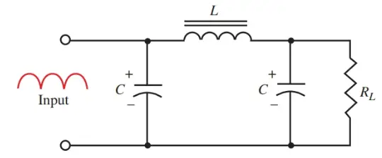
Figure 21. Pi (π) section filter.
When the first filtering component is a capacitor, the circuit is called a capacitor input filter. When the choke is the first filtering component, it is called a choke input filter, Figure 22. The choke input filter looks like an inverted L, so it is also called an L section filter. Several of these filter sections can be used in series to provide added filtering.
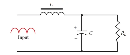
Figure 22. Choke input L filter
In the capacitor input filter, the capacitor charges to the peak voltage of the rectified wave. In the choke input, the charging current for the capacitor is limited by the choke. The capacitor does not charge to the peak voltage. As a result, the output voltage of the power supply using the capacitor input filter is higher than one using the choke input filter.
Things To Consider When Selecting a Power Supply
When selecting a power supply, several factors should be considered to ensure it meets the requirements of the application:
Voltage and Current Requirements: Determine the specific voltage and current levels needed to power the devices or components in the system. The power supply should be capable of providing these values within the specified tolerances.
Power Rating: Consider the overall power rating required by the system. This involves calculating the total power consumption of all components and selecting a power supply that can handle the load.
Efficiency: Look for power supplies with high efficiency ratings to minimize energy wastage and reduce operating costs. Higher efficiency also helps in dissipating less heat, leading to better reliability and longer lifespan.
Stability and Regulation: Ensure the power supply offers stable and well-regulated output voltage and current. This is important for maintaining the proper functioning of sensitive components and preventing damage due to voltage fluctuations.
Protection Features: Check for built-in protection mechanisms such as overvoltage protection, overcurrent protection, and short circuit protection. These safeguards help prevent damage to the power supply and the connected devices in case of unforeseen events.
Form Factor and Mounting: Consider the physical size, form factor, and mounting options of the power supply to ensure it fits within the available space and can be easily integrated into the system.
Reliability and Durability: Look for power supplies from reputable manufacturers known for their reliability and quality. Consider factors such as MTBF (Mean Time Between Failures) and warranty terms to gauge the reliability of the power supply.
Safety Standards and Certifications: Verify that the power supply complies with relevant safety standards and holds certifications like UL, CE, or RoHS. This ensures adherence to industry regulations and enhances the safety of the system.
Noise and Ripple: Consider the noise and ripple specifications of the power supply, especially in applications that require low noise levels or sensitive analog circuitry.
Cost: Evaluate the cost-effectiveness of the power supply while considering all the above factors. Balancing performance, reliability, and cost is crucial to ensure the best value for the specific application.
By carefully considering these factors, one can select a power supply that best suits the requirements of the system, ensuring stable and efficient power delivery.
Power Supply FAQs
What is a power supply?
A power supply is an electronic device that converts incoming electrical energy from a source into the appropriate voltage, current, and frequency required to power electronic devices or components.
What are the different types of power supplies?
Common types of power supplies include linear power supplies, switch-mode power supplies, uninterruptible power supplies (UPS), and programmable power supplies.
What is the difference between AC and DC power supplies?
AC (Alternating Current) power supplies provide electrical energy that periodically changes direction, while DC (Direct Current) power supplies provide a steady flow of electrical energy in one direction.
What is the role of voltage regulation in a power supply?
Voltage regulation ensures that the power supply delivers a stable output voltage regardless of input voltage fluctuations. It helps prevent damage to connected devices and ensures proper functionality.
How do I calculate the power requirements for my system?
To calculate power requirements, multiply the voltage and current requirements of each component and sum them up to determine the total power consumption of the system.
What is the efficiency rating of a power supply?
Efficiency rating indicates how effectively a power supply converts input power into usable output power. Higher efficiency ratings mean less energy loss and reduced operating costs.
Are all power supplies compatible with any device?
No, power supplies need to be selected based on the specific voltage, current, and connector requirements of the device. Using an incompatible power supply can damage the device or cause malfunctions.
What safety features should I look for in a power supply?
Important safety features include overvoltage protection (OVP), overcurrent protection (OCP), short circuit protection (SCP), and thermal protection. These safeguards help protect both the power supply and the connected devices.
Can a power supply be used worldwide?
Some power supplies are designed to work with a wide range of input voltages and frequencies, making them suitable for use in different countries. These are often referred to as universal power supplies.
Can I daisy-chain multiple power supplies?
In some cases, it is possible to daisy-chain multiple power supplies to provide power to a larger system or multiple devices. However, it is essential to ensure compatibility and proper load distribution.
Remember to consult the manufacturer’s documentation and seek professional advice when selecting and using power supplies to ensure safety and optimal performance.