In this article, we will discuss the operation/working principle of RC and RL high pass filters along with their cutoff frequencies.
As you know, a high pass filter is one that is designed to pass all frequencies above its cutoff frequency. High pass filters are formed by reversing the positions of the resistive and reactive components in the RC and RL low pass filters.
RC High Pass Filters
An RC circuit acts as a high pass filter when constructed as shown in Figure 1a. For comparison, an RC low pass filter is shown in Figure 1b. As you can see, the capacitor and resistor positions are reversed between the two circuits. In the high pass circuit, the capacitor is in the signal path and the resistor is the shunt component.
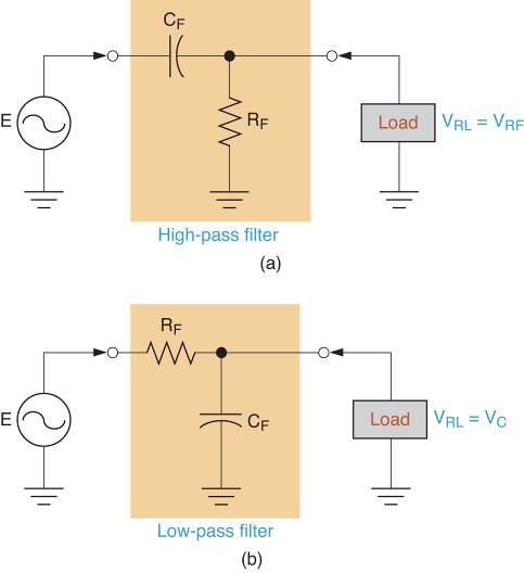
Figure 1: High-Pass vs Low-Pass Filters
The filtering action of the circuit in Figure 1a is a result of the capacitors response to an increase in frequency. This response is illustrated in Figure 2. The reactance curve (which we used to describe the low pass filter operation) shows that capacitive reactance varies inversely with operating frequency. With this in mind, look at the equivalent circuit shown in Figure 2b. As you can see, the near infinite reactance of the capacitor when the input frequency is 0Hz is represented as a break in the signal path. Therefore, the source is isolated from the load, and VRL = 0V.
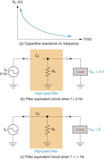
Figure 2: RC High-Pass Filter Operation
Assuming that the input frequency is near the high end of the reactance curve, XC can be assumed to be approximately 0Ω. With this in mind, look at the equivalent circuit as shown in Figure 2c. In this case, the low reactance capacitor is represented by a direct connection between the source and the load. As a result, the load voltage is approximately equal to the source voltage.
Between the extremes represented in Figure 2, lies a range of frequencies over which VRL decreases from VRL≅E to VRL = 0V.
RC High Pass Filter Cutoff Frequency (fC)
The cutoff frequency for an RC high pass filter is determined by using the same relationship, we established for the low pass filter. By Formula,
\[{{f}_{C}}=\frac{1}{2\pi RC}\]
We can use this relationship because only the component positions within the filter have changed. In other words, the relationship among fC, R, and C doesn’t change simply because the component positions have changed. Example 1 demonstrates the process used to calculate the cutoff frequency for an RC High-Pass filter.
Example 1
Calculate the cutoff frequency for the RC High-Pass filter in Figure 2a.
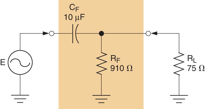
Figure 2a
Solution
First, the circuit resistance (as seen by the capacitor) is found as:
\[{{R}_{EQ}}={{R}_{F}}||{{R}_{L}}=\frac{75\times 910}{75+910}=69.3\Omega \]
Now, the cutoff frequency of the circuit can be found as:
\[{{f}_{C}}=\frac{1}{2\pi RC}=\frac{90.1\Omega }{2\pi \times 69.3\Omega \times 10\mu F}=230Hz\]
This result indicates that the power gain of the circuit is reduced to 50 % of its maximum value when the operating frequency decreases to 230 Hz. The frequency response curve for the circuit is shown in Figure 2b.
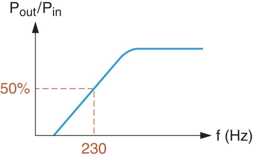
Figure 2b: Frequency response Curve
RL High Pass Filters
An RL circuit acts as a high pass filter when constructed as shown in Figure 3. In the circuit shown, the resistor is the series component and the inductor is the shunt component.
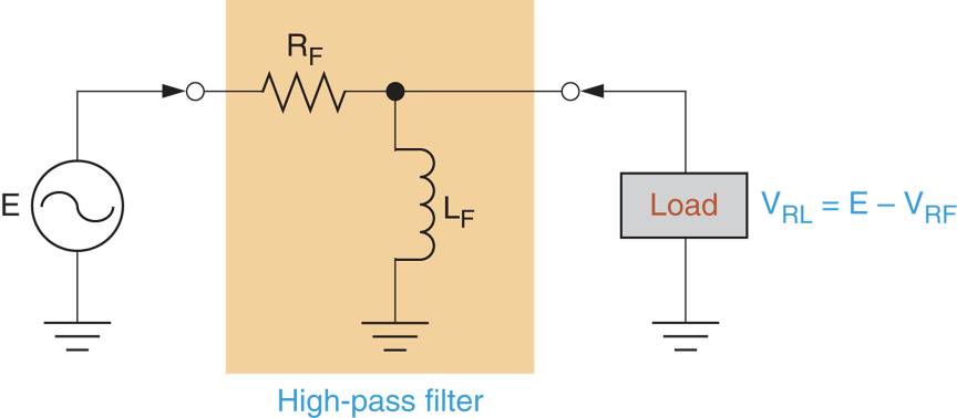
Figure 3: an RL High-Pass Filter
The filtering action of the circuit in Figure 3 is a result of the inductors response to a decrease in operating frequency. This response is illustrated in Figure 4. As the reactance curve indicates, XL approaches infinity as frequency increases.
If the input frequency decreases to 0Hz, the inductive reactance decreases to 0Ω. In this case, the equivalent circuit in Figure 4b applies. Ignoring the small amount of winding resistance in the coil, the shunt inductor is represented as a shorted path to ground. In this case, VRL = 0V.
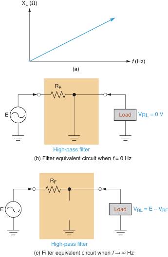
Figure 4: RL High-Pass Filter Operation
If the input frequency to the circuit increases, the reactance of the inductor increases until the component effectively acts as an open. If we assume that XL ≡ ∞Ω, the equivalent circuit in Figure 4c applies. As you can see, the inductor is represented as a break in the shunt component path. In this case, VRL = E –VRF. Between the extremes represented in Figure 4, lies a range of frequencies over which VRL decreases from E –VRF to 0V.
RL High Pass Filter Cutoff Frequency (fC)
The lower cutoff frequency for an RL high pass filter is determined by the inductor and the parallel combination of RF and RL. By Formula:
\[{{f}_{C}}=\frac{{{R}_{EQ}}}{2\pi L}\]
Where REQ = RF || RL.
Example 2 demonstrates the process used to calculate the cutoff frequency for an RL High-Pass filter.
Example 2
Calculate the cutoff frequency for the RL High-Pass filter in Figure 4a.
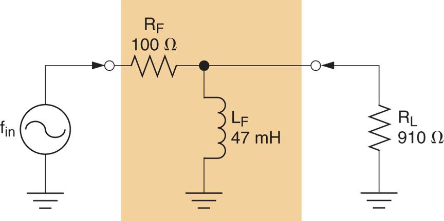
Figure 4a
Solution
First, the circuit resistance (as seen by the capacitor) is found as:
\[{{R}_{EQ}}={{R}_{F}}||{{R}_{L}}=\frac{100\times 910}{100+910}=90.1\Omega \]
Now, the cutoff frequency of the circuit can be found as:
\[{{f}_{C}}=\frac{{{R}_{EQ}}}{2\pi C}=\frac{90.1\Omega }{2\pi \times 47mH}=305Hz\]
This result indicates that the power gain of the circuit is reduced to 50 % of its maximum value when the operating frequency decreases to 305 Hz. The frequency response curve for the circuit is shown in Figure 4b.
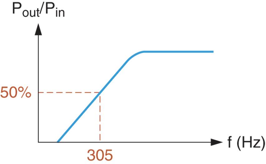
Figure 4b: Frequency Response Curve
As you can see, the analysis of an RL high pass circuit is identical to that of an RL low pass filter.
FAQs on RC High-Pass Filters
What is an RC high-pass filter?
– An RC high-pass filter is an electronic circuit that allows higher-frequency signals to pass through while attenuating or blocking lower-frequency signals. It consists of a resistor and a capacitor.
How does an RC high-pass filter work?
– It works by allowing high-frequency signals to flow through the capacitor, effectively bypassing the resistor. Low-frequency signals are attenuated as they cannot pass through the capacitor easily.
What is the cutoff frequency of an RC high-pass filter?
– The cutoff frequency is the point at which the filter starts attenuating the signal. For an RC high-pass filter, the cutoff frequency is given by fc = 1 / (2πRC), where R is the resistance and C is the capacitance.
What happens to the output voltage at frequencies below the cutoff frequency?
– Below the cutoff frequency, the output voltage of an RC high-pass filter decreases, and the filter acts as a signal attenuator.
Can you provide an example application of an RC high-pass filter?
– RC high-pass filters are commonly used in audio applications to remove or reduce low-frequency noise or to improve the clarity of audio signals by allowing only the higher-frequency components to pass.
FAQs on RL High-Pass Filters
What is an RL high-pass filter?
– An RL high-pass filter is an electronic circuit that allows higher-frequency signals to pass through while attenuating lower-frequency signals. It consists of a resistor and an inductor.
How does an RL high-pass filter work?
– It works by allowing high-frequency signals to flow through the inductor, effectively bypassing the resistor. Low-frequency signals are attenuated as they cannot pass through the inductor easily.
What is the cutoff frequency of an RL high-pass filter?
– The cutoff frequency is the point at which the filter starts attenuating the signal. For an RL high-pass filter, the cutoff frequency is given by fc = R / (2πL), where R is the resistance and L is the inductance.
What happens to the output voltage at frequencies below the cutoff frequency?
– Below the cutoff frequency, the output voltage of an RL high-pass filter decreases, and the filter acts as a signal attenuator.
Can you provide an example application of an RL high-pass filter?
– RL high-pass filters are used in various electronic circuits to protect sensitive components from low-frequency interference or to separate high-frequency signals from low-frequency noise in communication systems.