Two principal functions of a transistor are switching and amplification. In order to better understand what is meant by switching and amplification, we examine the following two examples.
Switching Function
Suppose that the current in a motor when working is 30 A. Dissimilar to a household device that you turn on and off by a simple switch, for such a relatively large load a relay is used to turn the motor on and off.
A relay consists of an electromagnet that can work with a low voltage (for better safety), for instance, 12 V. The electromagnet takes little current and can easily be activated even from a distance away without a concern about voltage drop in the wire.
- You May Also Read: Transistor | Working Principle | Properties
When activated, two (or more) sets of reeds make contacts. These reeds are connected to the motor and the electric supply (higher voltage). In this way, electricity is applied to the motor through an indirect switch. A person’s hand doesn’t have to even be near to the higher voltage line.
A relay is shown in Figure 1 together with a dime (10 cents American or Canadian coin), for size comparison.
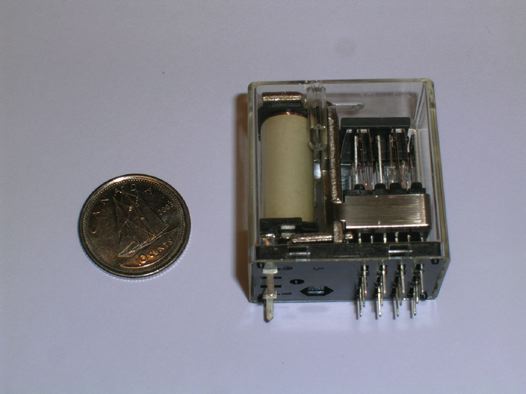
Figure 1 Picture of a small relay with eight sets of connections.
Figure 2 illustrates a schematic for a relay with only two connections. This relay can be used in two ways: when activated a connection is made, or an existing connection is broken open.
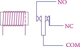
Figure 2 Schematic of the operation of a relay.
In the relay schematic “NO” stands for normally open and “NC” denotes normally closed. For making a connection, for instance in the case of a motor, the lines are connected between NO and the common connector (COM).
Similarly, if we need to stop a connection when the switch is activated, it is connected between the NC and the COM terminals. Figure 3 illustrates the use of a relay for switching a motor on and off.
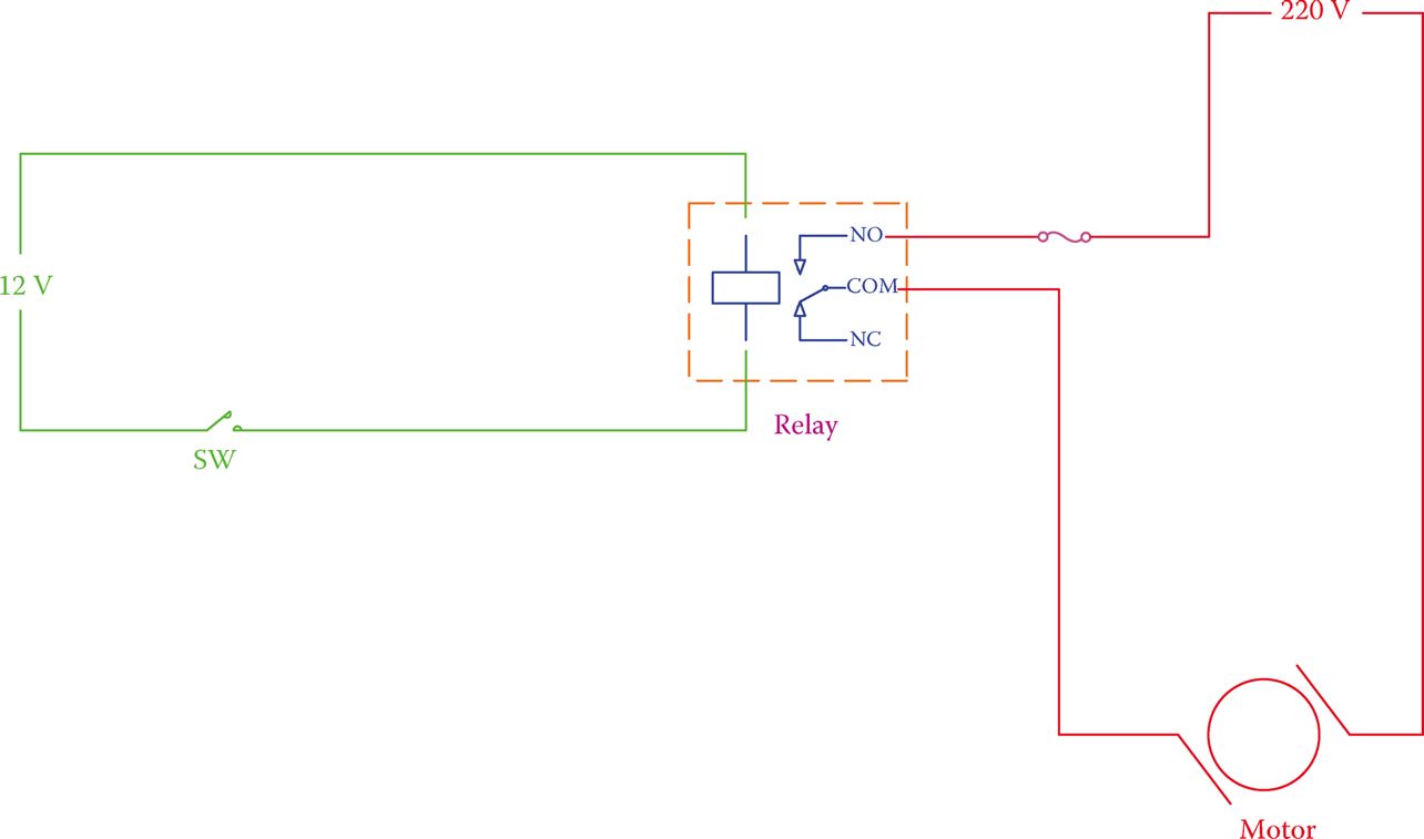
Figure 3 A relay used for activating a motor.
The advantages of using a relay are twofold:
- A person is not directly in contact with a switch carrying a relatively high voltage and/or a high current, which is accompanied by a spark when contact is made or broken.
- The switch can be installed in a remote position without the necessity for thicker wires of the motor circuit to be long. Thus, more expensive wiring and a larger voltage drop in the circuit (and consequently a waste of energy) are avoided.
Whereas a relay is a mechanical device, a transistor can perform the same job electronically and without any moving parts. It is smaller, too.
Amplification Function
Figure 4 shows a scenario in which by opening and closing a small valve and allowing a small flow of water a larger amount of water flow is controlled. This example shows another important function of a transistor, which is the amplification of a signal.
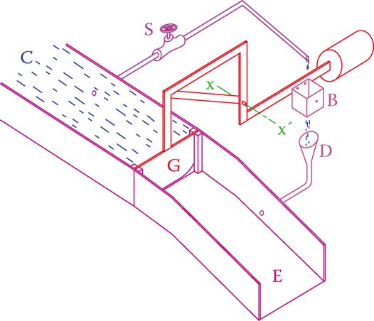
Figure 4 A hydraulic analogy of amplification function of a transistor.
Amplification is a major part of the function of almost all electronic devices, such as radio, TV, phone, voice, and data recorders.
- As illustrated in Figure 4, the round gate G can move up and down, thus adjust the flow from the channel C that connects to a water source. The gate movement is provided by a rotational motion of the gate assembly about axis xx′.
- Because of the counterweight on the other side of the axis, the gate can move up by a slight downward force on the right. The weight of the gate keeps it normally in the closed position and the counterweight W is such that little effort is required to move the gate about its axis.
- The bottom hole in the container B, attached to the lever bar between the gate and its counterweight, lets any water remaining in it be emptied and directed downstream through the funnel D. In this sense, the gate will close unless extra downward force exists on the right-hand side.
- By opening the valve S a small flow of water runs into B. This causes water to accumulate in B and make the counterweight side heavier, thus, pulling the gate upward and opening it. Consequently, a large flow of water is established from upstream to the E part of the channel.
- When the valve S is closed again, the water in B drains out and the gate goes back to its closed position.
By controlling the flow of water through the valve S we may control a larger flow of water through channel C.
In other words, the variation of the output in channel C is proportional and similar to the smaller flow controlled by the valve S.
In an amplifier, a low power signal is duplicated with much higher power. In other words, the input signal drives an amplifier to generate a more powerful signal with the same pattern at its output.
More power implies higher voltage, higher current, or higher both voltage and current. The power that is included in the output must be provided by the power supply powering a circuit.
In an amplifier, the power added to a signal is provided by the power supply.