In the following circuit, the transistor acts as a switch, in the same way, that a relay works. The advantage of a transistor to a relay is that a transistor is lighter, has less noise (if any at all), has no moving components, it is faster, consumes less energy and it is cheaper.
Note that in a complicated system, such as the operation of an elevator or a train, there can be hundreds or sometimes more than a thousand relays. In the past, these relay systems were common.
In addition to taking a much larger space and making noise by each relay when making contacts, after a while bugs could also make nests in the warm space between them and gradually disrupt the operation (the term bug and debug in computer terminology stems from here).
In the circuit shown in Figure 1, an NPN transistor is shown. The collector-base junction is reverse biased, as required, and a current never flows between the collector and the base.
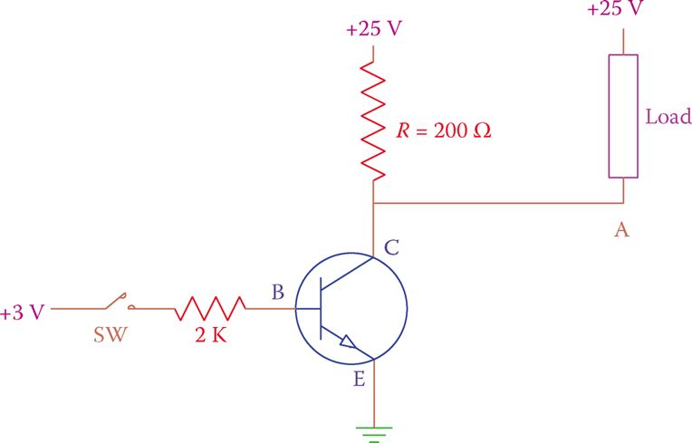
Figure 1 Transistor used as a switch.
The base-emitter junction is forward biased, but when the switch is open there is no current between the base and the emitter. Consequently, there is no current between the collector and the emitter because the transistor acts as an insulator.
If the voltage at point A (where the load is connected) is measured, it shows 25 V because there is no voltage drop in the 200 Ω resistor (due to carrying no current). The voltage difference across the load is zero and the load is not energized.
Closing the switch lets a current flow between the base and emitter. As mentioned earlier, this action turns on the internal collector-emitter connection and causes an electric current to flow from collector to the emitter. The magnitude of this current depends on the resistance R, which is 200 Ω here.
Ignoring the small voltage drops in the transistor, the C-E current is 125 mA (25 ÷ 200, based on Ohm’s law). The current flow of 125 mA causes a voltage drop of 25 V in the 200 Ω resistor. In such a case, if the voltage at point A is measured it must be 0 V.
Comparing with when the switch was open, now the voltage difference across the load is 25 V, and, therefore, the load is energized (note that when the load is connected to point A, the current through the emitter is the sum of the current through the 200 Ω resistor and the load current).
The scenario shown in Figure 1 is a practical example of the switching action of a transistor. Although it is a very simple example, it shows the principle of the way a transistor can be used for this type of application.
A similar circuit can be used for other applications such as counting people entering a library or the cars passing through a pathway by replacing the manual switch by a photocell (a resistor whose resistance changes with light and can be used as a light sensor), or by an automatic switch of a different type.
The switching action of a transistor can be at a very high frequency, like the radio, TV, and communication signals with megahertz frequencies.
In practice, we may want to avoid using more than one voltage source. This is very reasonable. Figure 2 illustrates the same setup as in Figure 1, but the voltage at the base is derived from the same power source supplying the load and the collector.
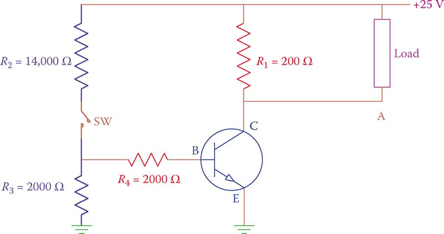
Figure 2 Providing base voltage by a voltage divider.
In this arrangement, the resistors R2 and R3 are so selected to provide the necessary voltage at the transistor base when the switch is closed.
The 14000 Ω and 2000 Ω resistors on the left establish a voltage divider. When the switch is closed a voltage equal to 1/8th (2000/[14000 + 2000]) of the total voltage provided to the load is applied to the base.
The above circuit can be used for automatic on-off switching of a light-bulb if a photocell is inserted as a switch in the circuit.
A photocell is like a variable resistor. When there is no light, it has a high resistance and in the presence of light, its resistance drops.
Consider the circuit shown in Figure 3. During the day the photocell (shown as a variable resistor) acts as a conductor, and, thus, the voltage at point N is zero (N is shorted to the ground). During the night, however, the resistance is considerable and the voltage at point N is equal to the voltage drop across the photocell resistance. As a result, current flows between the transistor base and emitter; this causes the transistor to turn on, as described.
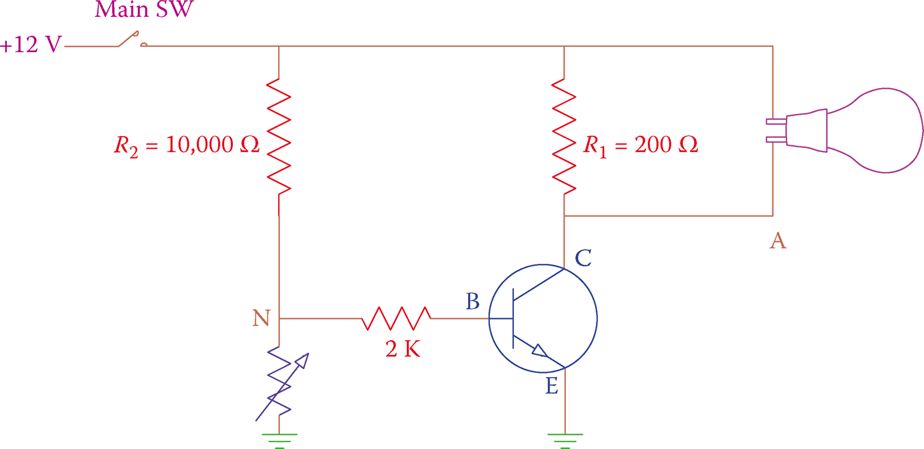
Figure 3 An automatic switch for turning a light on at night.
For other applications, alternatively, the voltage at the base terminal can be provided by a sensor that generates a signal with sufficient voltage. (Remember that the junction between B and E requires 0.7 V if made out of silicon, to conduct. The voltage at B, thus, must be more than that for a current to flow.)