Figure 1 shows the cross-sectional view of a single-phase induction motor. Consider the motor in Figure 1 at standstill. Current is applied to the windings, establishing two counter-rotating waves. As they sweep past the rotor bars they both try to start the machine but they cancel each other out. Thus, a single-phase machine produces no starting torque and must be started by auxiliary means.
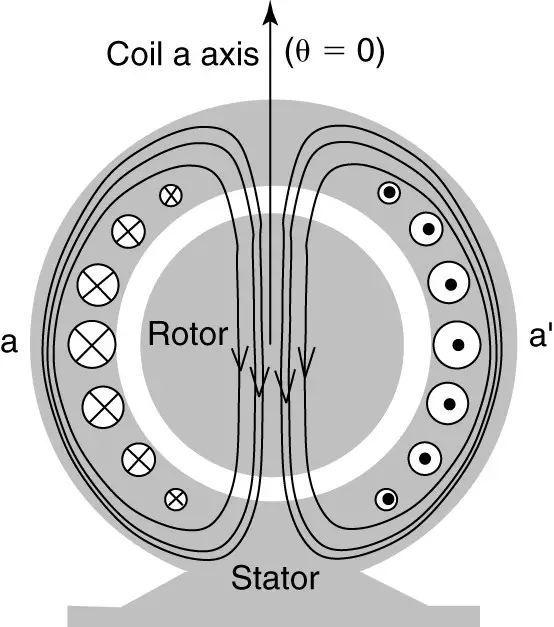
Figure 1: Single-phase induction motor cross section.
Figure 2 shows the torque vs. slip curve that we studied for the polyphase machine. We can consider this curve to represent the result of the forward traveling wave. The backward-traveling wave will produce a curve that is the mirror image of the origin.
Note that the positive torque of the forward-traveling wave is larger in magnitude than the negative braking torque of the reverse wave, once the machine is running. Thus, if we can start the machine, it will produce torque and keep running. In fact, since the rotor is turning when the motor runs, the forward torque is increased and the backward torque is decreased. Thus, the resultant torque is even better, approaching the performance of a polyphase machine with the same rotor and air gap flux density.
- You May Also Read: Three Phase Induction Motor Working Principle
Note that the torque shown is actually the average of the torque, which pulsates with a 120 Hz frequency (for a 60 Hz motor).
The power delivered to a single-phase circuit pulsates at twice the source frequency. Because torque is the power divided by the motor speed, the torque also pulsates.
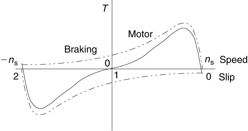
Figure 2: Forward, reverse, and combined torque-speed curves for a single-phase induction motor.
Oddly enough, to consider the operation of a single-phase motor, we need to consider a two-phase motor. Figure 3 shows a motor with two sets of coils physically separated by 90 electrical degrees.
The coils are shown concentrated in one slot but would actually occupy a number of slots, like the coil in Figure 1.
Consider the case when the machine is energized and currents flow in the coils. The currents are displaced by 90° in time. In other words, one coil has a sine current and the other coil has a cosine current.
At 0°, the current in the coil a is positive and is at a peak, while the current in coil b is zero. Thus, the N and S poles of the flux lie along the axis of the coil a.
At 45°, the two currents are equal. Thus, the peak of the flux wave lies be tween the coil axes. The N pole has rotated 45°. Continuing through one cycle of current, we find the magnetic field is rotating, just as in a three-phase machine. Because there is a rotating field, the machine will produce starting torque.
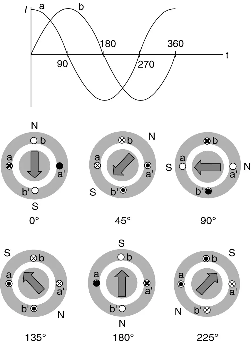
Figure 3: Two-phase induction motor currents and flux positions as functions of time.
Unfortunately, we don’t have two-phase currents available. We want a single-phase motor, and we presumably have only a single-phase voltage and current. Fortunately, we can imitate the two-phase machine by properly designing the windings of the single-phase machine.
Consider the two series R-L circuits shown in Figure 4. These two circuits can be used to represent the lumped equivalents of our two motor windings. Both have the same applied voltage and similar reactances, but one has a higher resistance.
The impedance angle, θ = tan-1(X/R), so the circuit with the larger resistance will have a smaller impedance angle, and the currents in the two circuits will be out of phase with each other. Let these currents be called I1, and I2.

Figure 4: Two coils with different impedances.
Using the circuit values given in Figure 4, we can calculate the magnitudes and angles as shown in equations 1 and 2.
$\begin{matrix} {{I}_{1}}=\frac{V}{{{Z}_{1}}}=\frac{120}{\left( 6.6+j10.6 \right)\Omega }=9.6\angle -{{58}^{o}}A & {} & \left( 1 \right) \\\end{matrix}$
$\begin{matrix} {{I}_{2}}=\frac{V}{{{Z}_{2}}}=\frac{120}{\left( 10.7+j8.4 \right)\Omega }=8.8\angle -{{38}^{o}}A & {} & \left( 2 \right) \\\end{matrix}$
The magnitude of the phase shift between I1, and I2 is the numerical difference between the angles obtained by equations 1 and 2. The phase shift is | -58° – (-38°) | or 20°.
We can make the resistance of a coil higher by using smaller-diameter wire, and the leakage inductance can be made smaller by placing it closer to the air gap in the stator slots.
Practically speaking, however, we can get no more than about 30° separation by changing the impedance of the coils. So by varying the impedance in the two windings, we could produce currents that are out of phase and produce a weak rotating magnetic field to start the motor. Because one of the coils has high resistance, it will produce a lot of heat and be inefficient. Thus, we would not want it to operate once the motor is started.
Instead of adding resistance to the second R-L circuit to produce a phase shift, we could add a capacitor and get even more phase shift. This concept is illustrated in Figure 5(a). Using the circuit values given in Figure 5, we can calculate the magnitude and angle of I3, as shown by equation 3.
The magnitude of the phase shift between I1, and I3 is | -58 °- (20°)| or 78°. Currents that are 90° out of phase will cause a rotating magnetic field. I2 and I3 are not 90° out of phase with but have components that are. I2N is 90° ahead of I1 and I3N is 90° ahead of I1, Figure 5 (b) illustrates this relationship. I3N is greater than I2N because the capacitor in Figure 5(a) produces a greater phase shift than the larger resistance in Figure 4(a).
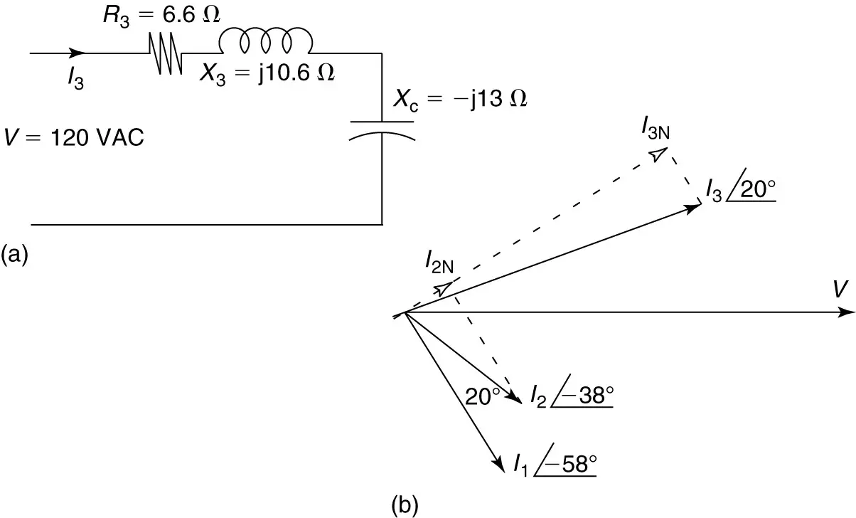
Figure 5: Using a capacitor to produce a phase shift.
- Start winding circuit.
- Phasor diagram, for circuits of Figures 4 and 5(a).
Both of these techniques (increased resistance and added capacitance) are used to make single phase induction motors.