The three-phase induction motor operates in some ways like a transformer. In the transformer, AC voltage is applied to the primary, which creates AC flux in the core. That flux links the secondary and induces a voltage of the same frequency, but with a voltage that depends on the transformer turns ratio.
The three-phase induction motor has voltage applied to the stator that creates a rotating flux wave. As that wave sweeps by the rotor bars, voltages are induced; however, the frequency of the voltage is determined by the slip of the motor. It turns out that the similarity extends to the equivalent circuits of the two devices.
Derivation of the Equivalent Circuit of Three-Phase Induction Motor
Figure 1 shows the construction of one phase of the armature winding. When a voltage is applied to the coil, current flows in the winding and flux is established, just as in the transformer. In Figure 1, the mutual flux is indicated by the solid lines passing through the middle of the rotor, while the leakage flux is indicated by dotted lines that do not cross the air-gap.
The air-gap in a motor is much larger than that of a transformer, which means the reluctance of the flux path will be much higher. Inductance, of course, is inversely proportional to the reluctance, so the inductance, and hence the reactance, will be smaller. As a result, the no-load current (or exciting current) will be significantly higher, percentage-wise, for an induction motor. Whereas the exciting current for a transformer is only a few percent of the rated current, the exciting current for an induction motor can be 40% or more of the rated current.
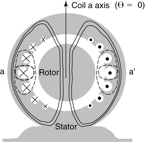
Figure 1. Mutual and leakage flux due to stator winding.
In developing the equivalent circuit for the induction motor, we can recall the equivalent circuit of the transformer. The primary circuit contained inductances to account for the leakage and mutual fluxes and resistances to account for the resistance of the primary winding and the core losses. The stator of the induction motor is essentially the same; there are mutual and leakage fluxes, winding resistance, and core losses due to hysteresis and eddy currents.
Figure 2 shows the equivalent circuit of one phase of the stator of the induction motor. It is assumed the windings are connected in wye, so the voltage applied to the circuit is a line-to-neutral voltage. The elements Rs and Xs are the stator winding resistance and leakage reactance, and Xm is the magnetizing reactance. This circuit is essentially the same as the primary circuit of a transformer. The only difference is we have not included a core loss resistance. The core losses are often accounted for separately and are thus not represented in the equivalent circuit.
Looking at the stator circuit of Figure 2, I1 is the current entering the winding. As already discussed, a significant current Im, is required to establish the magnetic field. The remaining current, I2, is the load portion of the stator current. The MMF of I2 will exactly cancel the MMF of the rotor current. In phasor notation, we can write,
\[\begin{matrix} {{V}_{1}}\text{ }=\text{ }{{E}_{1}}\text{ }+\text{ }{{I}_{1}}({{R}_{s}}\text{ }+j{{X}_{s}}) & {} & \left( 1 \right) \\\end{matrix}\]
Where E1 is the EMF induced in the stator coil by the mutual flux. We need to add the rotor to the equivalent circuit.
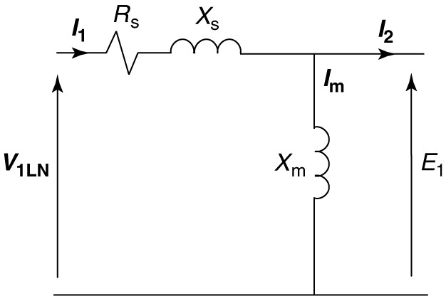
FIGURE 2 Induction motor stator equivalent circuit.
Looking at figure 3, as the stator flux sweeps by the rotor conductor, a voltage and current will be induced. If the rotor is not allowed to turn (blocked rotor), then the voltage and current induced in the rotor will have the same frequency as the stator.
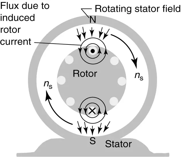
FIGURE 3 Induction of rotor currents by rotating stator magnetic field.
We have an unusual form of a transformer, in which the flux rotates around the rotor conductors. In the case of the transformer, we refer quantities from one side to the other using the turns ratio. Because most induction motors have squirrel cage rotors, it’s not easy to determine the number of turns on the rotor. Fortunately, we can avoid the problem by always working with quantities referred to the stator.
Figure 4 shows what’s happening when the rotor is blocked. As the stator field sweeps by the rotor conductors, a blocked rotor voltage, EBR (equal to E1), is induced. Since the coils are shorted, current flows through the resistance and leakage reactance of the rotor coils. In figure 4, Rr is the resistance of one phase of the rotor winding and Xr is the leakage reactance of the rotor when stator frequency currents flow in the rotor, which only happens when the rotor is stationary (slip=1.0). Of course, both Rr and Xr are referred to the stator by an appropriate turns ratio.
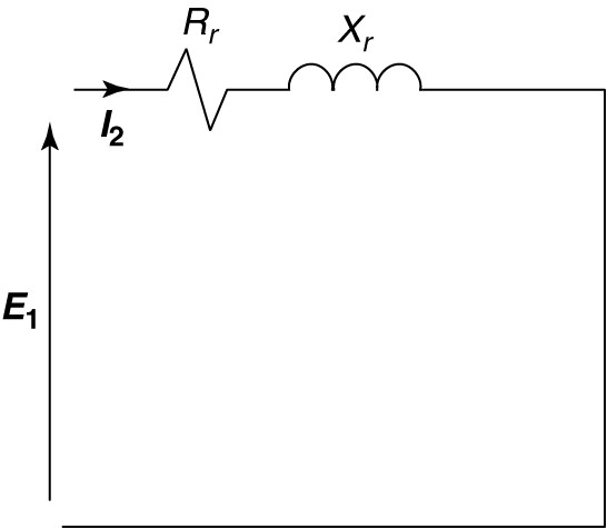
FIGURE 4 Rotor equivalent circuit at blocked-rotor condition.
For the induction motor to be of use to us, it must turn, which means the slip is less than 1.0. If the rotor is moving, two things happen:
- The relative velocity of the stator field and rotor coil is sns instead of ns. Recall that E=Blv. Thus, the voltage induced in the rotor will be sE
- Since the frequency of the rotor currents is sfs, the leakage reactance will have a value of sXr.
Replacing E1 by sE1, and Xr by sXr in Figure 4 yields the circuit shown in Figure 5, which is valid at any value of slip. In order to connect the rotor circuit of Figure 5 to the stator circuit of Figure 2, we must account for the different frequencies.
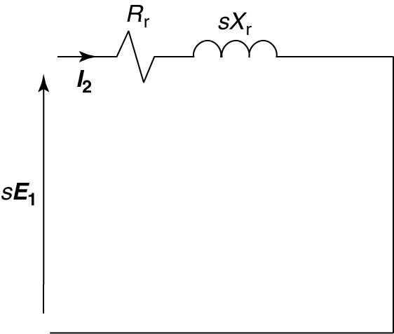
FIGURE 5 Rotor circuit at slip frequency.
Just as we referred impedances by the turns ratio, we can refer them by the frequency. From the circuit of Figure 5, we can write
\[\begin{matrix} \text{s}{{\text{E}}_{\text{1}}}\text{ + }{{\text{I}}_{\text{2}}}\text{(}{{\text{R}}_{\text{r}}}\text{ + js}{{\text{X}}_{\text{r}}}\text{)} & {} & \left( 2 \right) \\\end{matrix}\]
Dividing equation 7-8 by s yields
$\begin{matrix} {{E}_{1}}+{{I}_{2}}\left( \frac{{{R}_{r}}}{s}+j{{X}_{r}} \right) & {} & \left( 3 \right) \\\end{matrix}$
Equation 3 can be represented by the circuit of Figure 6, which is the rotor equivalent circuit referred to the stator both by turns ratio and by frequency.
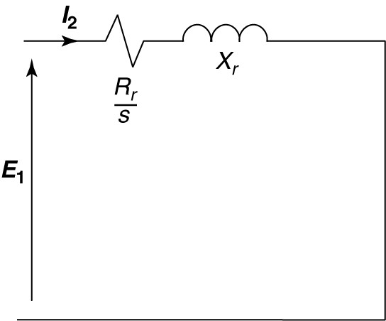
FIGURE 6 Rotor equivalent circuit referred to stator frequency.
This circuit can be connected to the stator equivalent circuit, but it is instructive to split the resistance into two separate components. For convenience, we can write:
\[\begin{matrix} \frac{{{R}_{r}}}{s}={{R}_{r}}+\frac{{{R}_{r}}}{s}-{{R}_{r}} & {} & \left( 4 \right) \\\end{matrix}\]
Combining the last two terms on the right side of equation 4 yields
\[\begin{matrix} \frac{{{R}_{r}}}{s}={{R}_{r}}+{{R}_{r}}\left( \frac{1-s}{s} \right) & {} & \left( 5 \right) \\\end{matrix}\]
Replacing the resistive element in Figure 6 by the two resistive elements on the right-hand side of equation 5 yields the rotor equivalent circuit shown in Figure 7. The reasons for this manipulation will be discussed shortly.
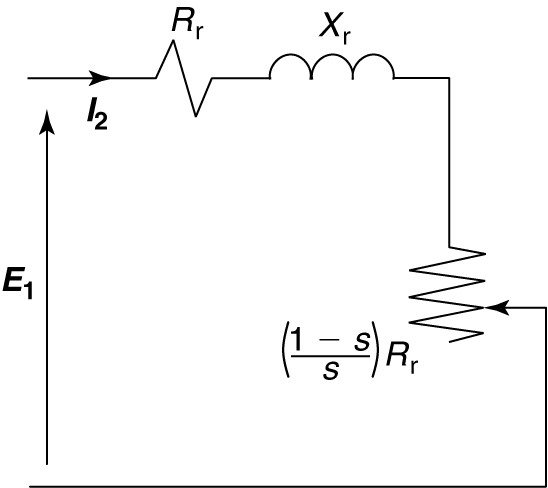
FIGURE 7 Rotor circuit referred to the stator, with rotor resistance split into two components.
Finally, by combining the rotor equivalent circuit of Figure 7 with the stator equivalent circuit of Figure 2, we obtain the steady-state equivalent circuit for one phase of a wye-connected induction motor, as shown in Figure 8.
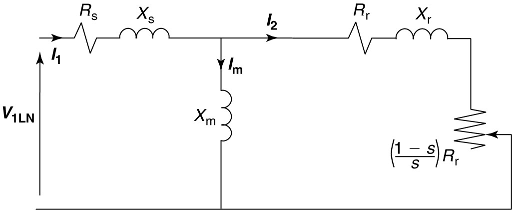
FIGURE 8 Per-phase induction motor equivalent circuit.
Locking again at the rotor part of the equivalent circuit in Figure 8, the resistor Rr represents the resistance of the rotor winding. The power used by it is the power lost in the resistive heating of the rotor winding. The additional resistive element on the right end is a function of the slip and the rotor resistance. It arises from the necessity to transform the rotor circuit not only by turns ratio but also by frequency. The power consumed in this element is the developed power of the machine.
Developed power is the power converted from electrical form to mechanical form and includes the load power plus mechanical losses such as friction and windage.
Subtracting the mechanical losses from the developed power would yield the shaft power, which is the actual power delivered to the load. Developed torque and shaft torque can be calculated from the developed and shaft power, respectively.
Induction Motor Equivalent Circuit Example
A four-pole, 60 Hz, 460 V, 5 HP induction motor has the following equivalent circuit parameters:
$\begin{matrix} \begin{matrix} {{R}_{s}}=1.21\Omega & {{R}_{r}}=0.742\Omega \\\end{matrix} & {{X}_{s}}=3.10\Omega \\ {{X}_{r}}=2.41\Omega & {{X}_{m}}=65.6\Omega \\\end{matrix}$
Find the starting and no-load currents for this machine.
Solution
At starting, the slip is 1.0, which means the load resistor in the equivalent circuit is a short (1-s=0). The current will be the voltage divided by the total impedance of the circuit. The input impedance can be found as:
\[{{Z}_{in}}=\left( {{R}_{s}}+j{{X}_{s}} \right)+\frac{j{{X}_{m}}\left( {{R}_{r}}+j{{X}_{r}} \right)}{{{R}_{r}}+j{{X}_{r}}+j{{X}_{m}}}\]
\[{{Z}_{in}}=\left( 1.21+j3.1 \right)+\frac{j65.6\left( 0.742+j2.41 \right)}{0.742+j2.41+j65.6}=5.75\angle {{70.72}^{o}}\]
\[{{I}_{st}}=\frac{{{V}_{LL}}}{\sqrt{3}{{Z}_{in}}}=\frac{460}{\sqrt{3}\left( 5.75\angle {{70.72}^{o}} \right)}=46.15\angle -{{70.72}^{o}}\]
For no-load, assume the slip is zero, which means the load element in the equivalent circuit will be an open circuit. We can thus find the input impedance:
${{Z}_{in}}=\left( {{R}_{s}}+j{{X}_{s}} \right)+j{{X}_{m}}$
${{Z}_{in}}=\left( 1.21+j3.1 \right)+j65.6=68.71\angle {{88.99}^{o}}$
\[{{I}_{nl}}=\frac{{{V}_{LL}}}{\sqrt{3}{{Z}_{in}}}=\frac{460}{\sqrt{3}\left( 68.71\angle {{88.99}^{o}} \right)}=3.87\angle -{{88.99}^{o}}\]