Learn about different types of single phase induction motors including split phase motor, capacitor start motor, permanent-split capacitor motor, Capacitor Start-Capacitor Run Motor, Shaded-Pole Motor, and Universal Motor.
Because residences and many commercial buildings have only single-phase power, single-phase AC induction motors have many applications. In the home, washers and dryers have a substantially single phase induction motor, about 1/3 horsepower.
The typical no-frost refrigerator has three motors- one which is an integral part of the compressor unit, one for the fan to circulate the cold air, and one to run the timer for the defrost cycle.
Forced-air heating systems have a fan motor. Kitchen appliances, such as blenders and mixers, tools, such as drill motors, and other devices could easily have several dozen single phase induction motors.
Split Phase Induction Motor
Figure 1 illustrates the split-phase induction motor. The split-phase motor relies solely on differences in the resistance and reactance of the windings to produce a phase shift.
There is a centrifugal switch in the auxiliary winding circuit that opens as the motor approaches full speed. The split-phase motor is characterized by a relatively low starting torque, perhaps 100%-150% of rated torque.
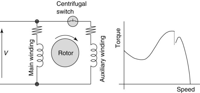
FIGURE 1: Split-phase induction motor (SPIM) circuit (wiring) diagram and torque-speed curve.
Capacitor-Start Induction Motors
Figure 2 illustrates the capacitor-start induction motor. The capacitor-start motor uses a capacitor to produce a phase shift.
It is sized to provide high starting torque, as much as 300% of rated torque. The capacitor is not designed for continuous operation, so there is a centrifugal switch in this motor to remove the auxiliary winding after start-up.
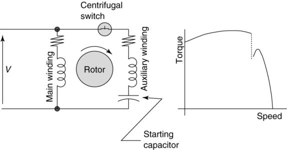
FIGURE 2: Capacitor-start induction motor (CSIM) circuit (wiring) diagram and torque-speed curve.
Single-phase motors are inherently noisier and less smooth running than polyphase motors. Because there is a backward-rotating component of flux, there are pulsating torques, so the torque-speed curve is really just a representation of the average torque.
If we left a capacitor in the auxiliary winding after the motor was started, we could approximate two-phase operation and have a smoother-running, quieter motor.
Permanent Split-Capacitor Motor
Because the reactance of the motor winding and the capacitor are both functions of frequency, we can only obtain true two-phase operation at one motor speed for a given capacitor.
The permanent split-capacitor motor shown in Figure 3 has a capacitor sized for running, which means the starting torque is very low, perhaps only 75% of rated torque.
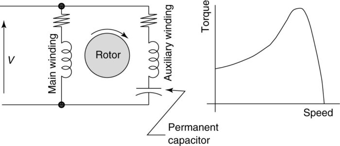
FIGURE 3: Permanent split-capacitor (PSC) motor circuit (wiring) diagram and torque-speed curve.
The reversing permanent split-capacitor motor illustrated in Figure 4 uses two identical windings, a single capacitor, and a selector switch. The selector switch is used to switch the capacitor between the two windings.
Switch position 1 places the capacitor in series with winding b, and switch position 2 places the capacitor in series with winding a. The effect is to reverse the direction of rotation.
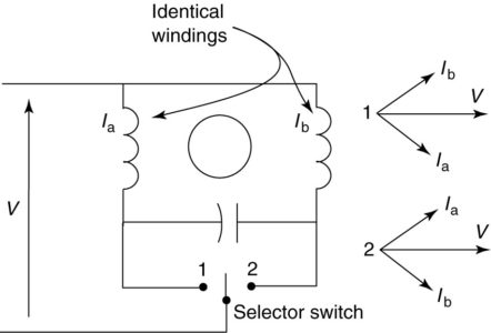
FIGURE 4: Reversing permanent split-capacitor motor circuit (wiring) diagram
Capacitor Start-Capacitor Run Motor
To provide both good starting torque and good running performance, two capacitors could be used, as shown in Figure 5.
One capacitor provides high starting torque and is switched out when the motor reaches rated speed. The other, smaller capacitor remains in the circuit at all times. This type of motor is called a capacitor start-capacitor run motor.
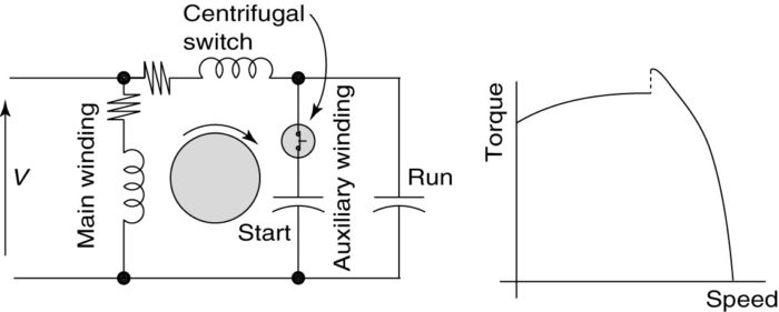
FIGURE 5: Capacitor start capacitor run motor circuit (wiring) diagram and torque-speed curve.
Figure 6 is a photograph of a capacitor-start induction motor. The characteristic hump on the top of the motor is where the capacitor is located.
A split-phase induction motor will not have the hump because it does not have a capacitor. Figure 7 shows a photograph of a run capacitor.
Figures 8 and 9 are photographs of a rotor and stator equipped with a centrifugal switch. In Figure 8, the weights on the shaft swing out when the motor nears synchronous speed, causing the washer at the end to move toward the squirrel cage. That releases the switch that is mounted in the end bell of the motor, as shown in Figure 9.
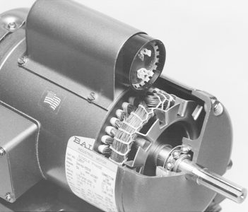
FIGURE 6: Capacitor-start induction motor (CSIM). (Courtesy Baldor Electric Company)
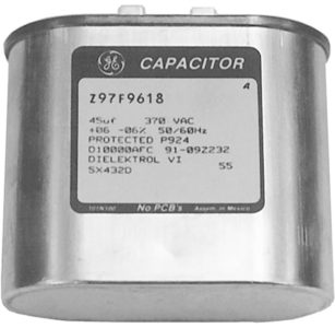
FIGURE 7: a Run capacitor for PSC, or two-capacitor, motor.
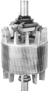
FIGURE 8: Squirrel-cage rotor with rotating part of the centrifugal switch.
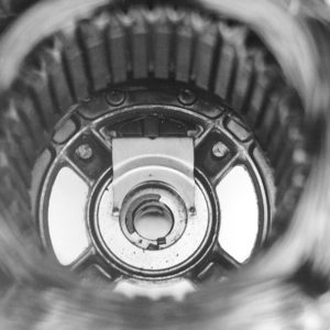
FIGURE 9: Stationary part of the centrifugal switch in stator end bell.
Shaded-Pole Motor
Another member of the induction motor family is the shaded-pole motor. Typically, the shaded- pole motor is a very small machine (0.05 HP) used for easy-to-start loads like a fan.
Although not very efficient, it is a simple, cheap, and rugged machine. The fact that it is a small machine tends to offset its inefficiency. Figure 10 illustrates the principle of operation of a shaded- pole motor.
Shaded Pole Motor Construction
Part of the stator iron is wrapped with several short-circuited turns of copper conductor. According to Faraday’s law, the current in the shorted turns (shading coil) will produce a flux that will oppose any change of flux through it.
The left copper ring in Figure 10 shows the flux increasing through the ring. The change in flux induces a current in the shorted ring that opposes the change in flux, as shown.
The ring on the right shows what happens when the flux is decreasing through the ring. Now, the induced current attempts to maintain the flux in the ring. The lower half of Figure 10 shows one type of shaded-pole motor. The laminations are rectangular, with a cutout for the coil and another for the rotor, as shown. The coil is wound through the rectangular window in the stack of laminations.
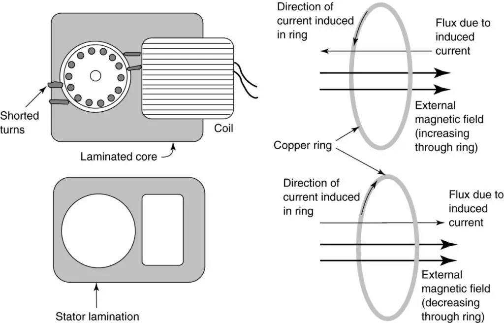
FIGURE 10: Construction of a shaded-pole motor and operation of a shading pole.
Shaded Pole Motor Operation
The operation of the rectangular shaded pole motor is shown in Figure 11.
The first view (1) shows the motor when the current is increasing in the positive direction, as shown on the sine wave in the middle of the figure. During this interval, most of the flux passes through the center of the rotor and not through the shaded poles.
In the second interval, the current and flux are decreasing. Thus, the shaded pole attempts to maintain the flux, and most of the flux passes through the shaded poles. Note that as a result, the general direction of the flux has changed from towards the upper-left corner to the lower-left comer.
The process continues in views 3 and 4, and the result is a quasi-rotating field, which is enough to start and run the motor. The direction of rotation of a shaded-pole motor can be changed only by physically disassembling the motor and reversing the direction of the rotor.
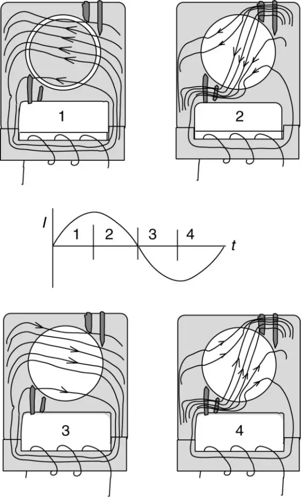
FIGURE 11: Flux patterns in a shaded-pole motor.
The major advantage of the shaded-pole motor is it is very cheap. Many readers may have purchased a large fan at a discount store with multiple speeds for less than $15.00.
Because the shaded-pole motor operates at larger values of slip, speed control is also very cheap. Recall the equation for the voltage induced in a coil:
${{E}_{rms}}=4.44fN{{\phi }_{\max }}$
Shaded Pole Motor Speed Control
The voltage applied to the motor is, of course, constant (or at least almost so). If the number of turns in the winding were varied, then the flux would vary in the opposite direction. Thus, the speed of a shaded-pole motor can be controlled by changing the number of volts per turn of the stator winding, as illustrated in Figure 12.
Speed control is accomplished by using a tapped winding and a selector switch, as shown in Figure 12(a). Increasing the number of turns will result in less voltage per turn and less flux; less flux means less torque from the machine, resulting in operation at a higher value of slip and a slower speed.
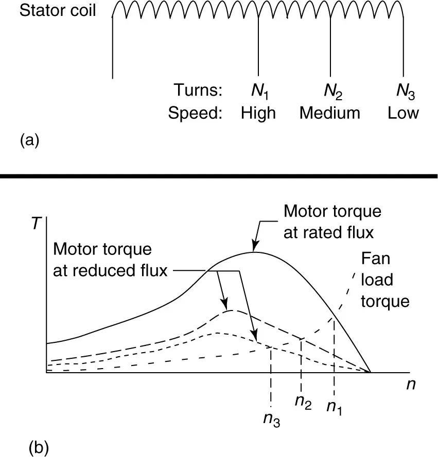
FIGURE 12: Speed control of a shaded-pole motor.
Figure 13 is a photograph of the rotor and stator from a shaded-pole motor. Figure 14 is a photograph of a round shaded-pole motor with six salient poles on the stator.
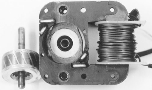
FIGURE 13: Shaded-pole rotor and stator.
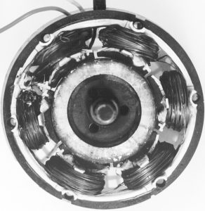
FIGURE 14: Round shaded-pole motor.
Universal Motor
The universal motor is essentially a DC motor designed to run on AC. Because the field coils see an AC current, the stator must be made of laminations just like the armature. The armature and field are connected in series, as shown by the cross-sectional view in Figure 15.
When the current changes polarity, the flux created by both windings also changes polarity, resulting in the unidirectional rotation.
By following the current flow in each view of Figure 15 and applying the left-hand rule for motors, it can be seen that the direction of rotation is always counterclockwise for this particular winding arrangement.
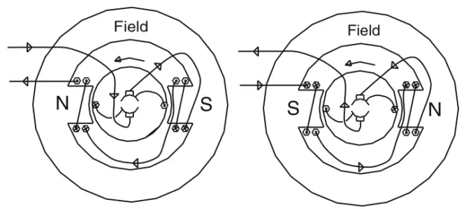
FIGURE 15: Universal motor with AC source.
The universal motor, like a series DC motor, has a very high no-load speed that drops rapidly as the load increases. Figure 16 shows the speed-torque characteristics of a universal motor.
The no-load speed may be so high that the centrifugal force may pull the motor apart. Thus, the motor should be connected to some mechanical load at all times.
Unlike the induction motor variations, the universal motor is not limited to operating below synchronous speed. Universal motors are used in portable drills, saws, routers, vacuum cleaners, and similar applications.
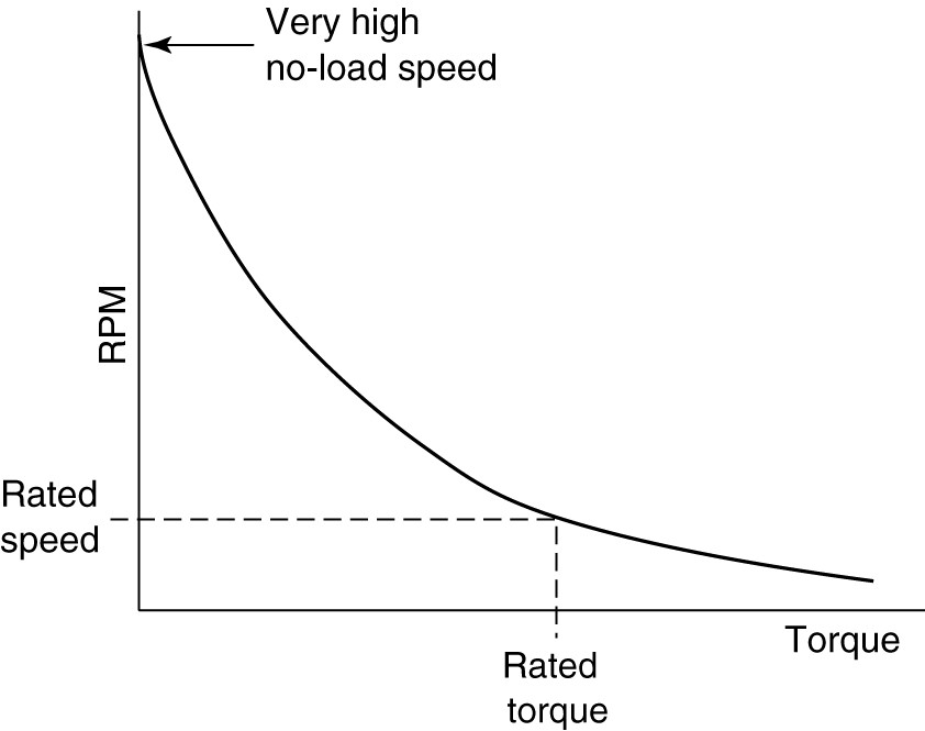
FIGURE 16: Torque-speed characteristic for a universal motor.
The direction of rotation of a universal motor can be changed by reversing the relative poles of the rotor and stator. This is accomplished by changing the brush connections at the commutator to allow the current to reverse its direction in the rotor while continuing to flow in the same direction in the stator. The speed of a universal motor is typically controlled by means of electronic devices.
Single-Phase Induction Motors FAQs
What is a single-phase induction motor?
A single-phase induction motor is an electric motor that operates on single-phase power supply. It is widely used in various applications, including home appliances, small machinery, and HVAC systems.
How does a single-phase induction motor work?
Single-phase induction motors rely on the principle of electromagnetic induction to generate a rotating magnetic field. The motor’s stator windings create a magnetic field that interacts with the rotor’s currents, causing it to rotate.
What are the main components of a single-phase induction motor?
The main components of a single-phase induction motor include the stator (with the primary and auxiliary windings), rotor, bearings, and a housing or frame.
What are the advantages of single-phase induction motors?
Single-phase induction motors are simple in design, reliable, and cost-effective. They require minimal maintenance and are suitable for a wide range of applications.
Can single-phase induction motors run in both directions?
No, single-phase induction motors typically rotate in one direction, determined by the motor’s design and winding configuration. Reversing the rotation direction often requires additional external components or specialized motors.
How can I control the speed of a single-phase induction motor?
Unlike three-phase motors, controlling the speed of a single-phase induction motor can be challenging. However, methods such as using variable frequency drives (VFDs) or changing the number of poles can provide speed control to some extent.
Can single-phase induction motors be used for heavy loads?
Single-phase induction motors are generally suitable for light to moderate loads. For heavy loads, it is often more practical to use three-phase induction motors due to their higher power output and efficiency.
What are some common applications of single-phase induction motors?
Single-phase induction motors find application in a wide range of devices and systems, including fans, pumps, air conditioners, refrigerators, washing machines, small tools, and various household appliances.
Do single-phase induction motors require any special starting mechanisms?
Single-phase induction motors often require additional starting mechanisms to overcome the initial lack of rotating magnetic field. Common starting methods include using capacitors (capacitor-start or capacitor-start-capacitor-run motors) or centrifugal switches.
Can single-phase induction motors be used with renewable energy sources?
Yes, single-phase induction motors can be utilized with renewable energy sources such as solar panels or wind turbines. However, additional components like inverters or converters may be required to convert the variable DC or AC output to the suitable power supply for the motor.