An analog multimeter is a meter that can measure two or more electrical properties and display the measured properties along calibrated scales using a pointer.
Analog multimeter uses an electromechanical component called a D’Arsonval movement to move the pointer along the scales to display measured values when the test leads are connected to a circuit, device, or circuit component.
As shown in Figure 1, most analog multimeters have several calibrated scales for the single-meter movement as shown in Figure 1. On the GM Instruments VOM shown, the calibrated scales correspond to the different function/range switch settings that include OFF; AC V (volts), Batteries Check, Ohms, DC A (amps), and DC V (volts). The meter is normally stored with the function/range switch set to the OFF position.
The different function/range switch settings require placement of the test leads in two of the three jacks. The lead jacks are identified as: the DC 10A (DC 10-amp scale) jack; the + V-W-A (volt-ohms-DC mA) jack; and the – COM (Common) jack.
Most measurements are taken with the red test lead plugged into the + V-W-A jack, and the black test lead plugged into the – COM jack. For the DC amperage scales, only the red test lead is moved to the appropriate jack.
Linear or Nonlinear Scale
A linear scale is a scale that is divided into equally-spaced segments. A nonlinear scale is a scale that is divided into unequally-spaced segments.
Normally, the voltage and amperage scales on an analog multimeter are linear, whereas the ohmic scales are nonlinear.
When using an analog multimeter, the correct scale must be used to obtain either a voltage, current, or ohmic reading.
On the GM Instruments VOM shown in Figure 1, the AC voltage settings include the 1000-volt scale; the 250-volt scale; the 50-volt scale; and the 10-volt scale. On the scales display, only the 250-volt scale, the 50-volt scale, and the 10-volt scale are shown. The 10-volt scale doubles for both the 10-volt and the 1000-volt scales: the correct voltage reading is according to the function/range-switch setting.
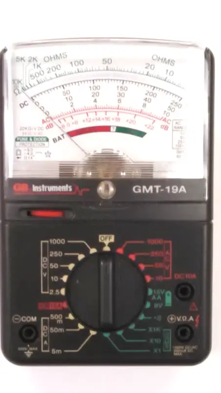
Figure 1. Although replaced with DMM in many hand-held operations, analog multimeter or VOM is still around
Analog Multimeter Scales
On the GM Instruments VOM shown in Figure 1, there is only one log scale (nonlinear) for the resistance measurements, although there are three resistance scales indicated on the function/range switch. The three ranges indicated are (R) ´ 1K; (R) ´ 10; and (R) ´ 1.
The measured resistance value on the scale readout is the (R) or resistance value that must be multiplied by either 1000 (1K), 10, or 1, according to which resistance range was selected.
The DC voltage settings include the 1000-volt scale; the 250-volt scale; the 50-volt scale; and the 10-volt scale. On the scales display, the same 250-volt, 50-volt, and 10-volt scales are shown double for both AC voltage measures and DC voltage measures. The 10-volt scale doubles for both the 10-volt and the 1000-volt scales: the correct voltage reading is according to the function/range-switch setting.
The analog scales on an analog multimeter are normally divided using primary divisions, secondary divisions, and subdivisions.
When reading an analog scale, the primary, secondary, and subdivision readings are added to determine the voltage, current, or resistance reading.
On the GM Instruments VOM shown in Figure 2, a measure is indicated by the pointer located about midway on the scale display. What is being measured is totally dependent on what is not shown in the picture, and that is the selected setting of the function/range switch.
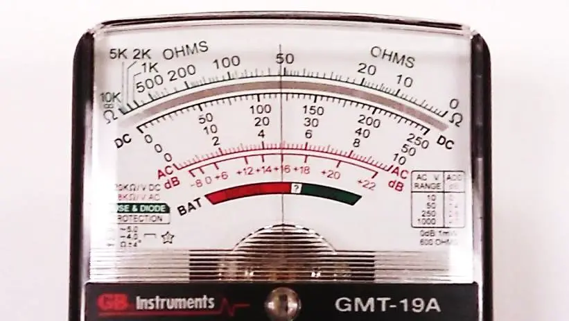
Figure 2. Taking a reading with an analog multimeter
Analyzing from top to bottom on the scale display:
The top scale is the ohmic or resistance scale. The pointer needle is past 50 but less than 100. The primary divisions on the scale are 50 and 100. Between 50 and 100, a difference of 50 exists, which represents the secondary divisions. With the five secondary divisions, each of these secondary divisions indicates 10 to be added to the 50. Each secondary division of 10 contains one subdivision, so each subdivision indicates 5 to be added to the 50.
In Figure 2, since the pointer is between 50 and the first subdivision and is almost touching the first subdivision, the readout is approximately 54. Now according to the function/range-switch setting, the readout is either 54Ω, 540Ω, or 54 kΩ (54,000Ω).
The Function/Range Switch in an Analog Multimeter
If the function/range switch is set on either an AC or DC voltage range, the three voltage scales are analyzed in the same manner.
The DC scale is above the three voltage-range scales, whereas the AC scale is below the three voltage-range scales. Both the DC and AC voltage scales contain five primary divisions, with one secondary division and four subdivisions between each primary and secondary division.
Disadvantages
The pointer needle is between the 100 and 150 readouts on the 250-volt scale. There are 50 volts between the 100- and 150-volt readouts. The single secondary division in the center between these two readout points divides the 50 volts in half to 25 volts. Between the 100 readouts and the center secondary division, the 25 volts are divided into four 5-volt subdivisions. On the DC voltage scale, the readout appears to be exactly 120 volts.
On the AC voltage scale, the pointer needle appears to be about midway between the last subdivision and the center secondary division: the AC voltage readout appears to be about 123 volts.
A phenomenon referred to as “parallax error” occurs when reading the pointer against the selected scale on an analog multimeter:
If you read the scale from a side-angle view, a measured value of 120 volts may appear as 123 volts or 117 volts, according to which side of the pointer you are viewing from. The 120-volt reading only occurs when you are looking straight on at the pointer suspended over the scale.
The pointer needle is between the 20 and 30 readouts on the 50-volt scale. Ten volts are between the 20- and 30-volt readouts. The single secondary division in the center between these two readout points (20 and 30) divides the 10 volts in half to 5 volts. The four subdivisions between the 20 readouts and the center secondary division divide the 5 volts into 1-volt subdivisions.
On the DC voltage scale, the readout appears to be exactly 24 volts. On the AC voltage scale, the pointer needle appears to be about midway between the last subdivision and the center secondary division: the AC voltage readout appears to be about 24.5 volts.
The pointer needle is between the 4 and 6 readouts on the 10-volt scale. There are 2 volts between the 4- and 6-volt readouts. The single secondary division in the center between these two readout points divides the 2 volts in half. The four subdivisions between the 4 readouts and the center secondary division divide the 1 volt into 0.2-volt or 2/10ths of a volt subdivision.
On the DC voltage scale, the readout appears to be exactly 4.8 volts. On the AC voltage scale, the pointer needle appears to be about midway between the last subdivision and the center secondary division: the AC voltage readout appears to be about 4.9 volts.
If the 1000-volt scale is selected, the readout appears to be exactly 480 volts on the DC voltage scale and about 490 volts on the AC voltage scale.
Conclusion
Due to the many problems associated with an analog multimeter, as for as selecting the wrong scales (wrong function setting), especially when the meter is set on an ohmic scale and you are attempting to take a voltage reading, these meters have been known to explode. Handheld analog multimeters have all been replaced with digital multimeters.
Top Selling Electrical Testing Tools

Fluke 101 Basic Digital Multimeter Pocket Portable Meter Equipment Industrial (Original Version)
$43.49 (as of April 3, 2024 21:21 GMT +00:00 - More infoProduct prices and availability are accurate as of the date/time indicated and are subject to change. Any price and availability information displayed on [relevant Amazon Site(s), as applicable] at the time of purchase will apply to the purchase of this product.)
Fluke T5-600 Electrical Voltage, Continuity and Current Tester, Measures Up To 100 A Without Contact, Automatically Select AC/DC Voltage For Tests, Includes Detachable SlimReach Probe Tip
$148.58 (as of April 3, 2024 21:21 GMT +00:00 - More infoProduct prices and availability are accurate as of the date/time indicated and are subject to change. Any price and availability information displayed on [relevant Amazon Site(s), as applicable] at the time of purchase will apply to the purchase of this product.)
Mr. Pen- Voltage Tester, Electrical Tester, Non Contact Voltage Tester, Tester Electric, Electric Tester Pen, Voltage Detector, Electrical Testers, Voltage Tester Pen, Electricity Tester, Power Tester
$9.85 (as of April 3, 2024 21:21 GMT +00:00 - More infoProduct prices and availability are accurate as of the date/time indicated and are subject to change. Any price and availability information displayed on [relevant Amazon Site(s), as applicable] at the time of purchase will apply to the purchase of this product.)
Premium LED Bulb Automotive Circuit Tester, 6-24V Test Light with 135 Inch PU Extended Spring Wire, Sharp Hard Steel Probe Vehicle Circuits Low DC Voltage Light Tester
$9.99 (as of April 3, 2024 21:21 GMT +00:00 - More infoProduct prices and availability are accurate as of the date/time indicated and are subject to change. Any price and availability information displayed on [relevant Amazon Site(s), as applicable] at the time of purchase will apply to the purchase of this product.)