A voltmeter is a basic device used for the measurement of electric potential or voltage, in volts.
As discussed in ammeter section, any basic meter mechanism has a voltage Vm across its terminals when a full-scale current Im, flows through the meter. It follows that basic meter mechanism can be calibrated in micro-volts, milli-volts, or volts, depending on the voltage needed to produce a full-scale deflection. The symbol for the voltmeter is a circle with the enclosed letter V, as indicated in Figure.

A voltmeter is connected across (parallel to) the component or a specific portion of a circuit for which the voltage (potential difference) is being measured out.
Just like a DC ammeter, a DC voltmeter also has polarity signs on it; therefore, one has to connect the plus (+) terminal of the voltmeter to the higher point of potential and the minus (-) terminal to the lower point of potential in order to obtain an upscale meter deflection.
- You May Also Read: Ammeter Definition and Working Principle
An AC voltmeter does not have any polarity signs on it, but the instrument is still connected in parallel to the component for which the voltage is desired. As a voltage measurement does not involve breaking the circuit, the voltmeter needs to be connected only when a reading is desired.
A voltmeter with a higher voltage range, V, is constructed by connecting a resistance, Rsc in series with a meter mechanism, having a full-scale voltage capability of Vm as shown in the following Fig.
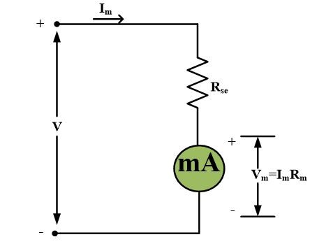
The series resistance is called a multiplier; its value is determined from the voltage equation.
$V={{I}_{m}}{{R}_{se}}+{{V}_{m}}$
Multiple scale voltmeters are constructed either by using switching arrangements or multiple terminals.
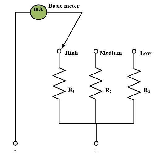
In above figure, each of the multiplier resistors is separately calculated and are then selected by a non-shorting switch.
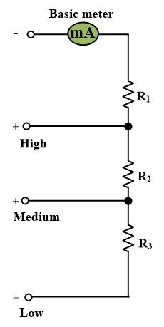
The multiplier resistors for above figure are calculated by first evaluating the resistance needed for the lowest range. The additional resistance needed for each higher range is then determined.
Voltage Sensitivity
It is defined as the reciprocal of the current necessary for full-scale deflection.
$Sensitivity=\frac{1}{{{I}_{m}}}~\Omega /Volt$
Where Im is the full-scale current. A smaller meter current results on a larger voltage sensitivity. The actual voltmeter resistance equals the sensitivity times the full-scale voltage. The voltmeter resistance remains constant even through the voltage reading may not be a full-scale reading.
Example
A multi-range voltmeter with 50 and 250 V ranges use a 50 μA meter mechanism.
(a) What is the sensitivity?
(b) What resistance does the voltmeter present n each range?
Solution
(a)
$Sensitivity=\frac{1}{{{I}_{m}}}=\frac{1}{50*{{10}^{-6}}}=20{}^{k\Omega }/{}_{V}$
(b)
\[R=sensitivity\text{ }*\text{ }range\]
50 V range:
$R=\left( 20*{{10}^{3}} \right)\left( 50 \right)=1*{{10}^{6}}=1~M\Omega $
250 V range:
$R=\left( 20*{{10}^{3}} \right)\left( 250 \right)=5*{{10}^{6}}=5~M\Omega $
Top Selling Electrical Testing Tools

AWBLIN Automotive Test Light 3-60V DC Digital LED Circuit Tester, Heavy Duty Light Tester with Voltmeter, Auto Bidirectional Voltage Tester Electric Test Pen
$21.99 (as of April 3, 2024 21:21 GMT +00:00 - More infoProduct prices and availability are accurate as of the date/time indicated and are subject to change. Any price and availability information displayed on [relevant Amazon Site(s), as applicable] at the time of purchase will apply to the purchase of this product.)
Plusivo Digital Multimeter Tester 2000 Counts AC DC Voltmeter Ohm Volt Amp Multi Meter Measures Voltage, Resistance, Current, Continuity, Tests Battery and Diode with Test Probes for Electricians
$12.99 (as of April 3, 2024 21:21 GMT +00:00 - More infoProduct prices and availability are accurate as of the date/time indicated and are subject to change. Any price and availability information displayed on [relevant Amazon Site(s), as applicable] at the time of purchase will apply to the purchase of this product.)
AstroAI Multimeter Tester, TRMS 4000 Counts Volt Meter Auto-Ranging Ohmmeter Digital 1.5v/9v/12v Battery Voltage Tester Measure Voltage Current Resistance Diodes Continuity Capacitance with NCV
$19.99 (as of April 3, 2024 21:21 GMT +00:00 - More infoProduct prices and availability are accurate as of the date/time indicated and are subject to change. Any price and availability information displayed on [relevant Amazon Site(s), as applicable] at the time of purchase will apply to the purchase of this product.)
Sperry Instruments STK001 Non-Contact Voltage Tester (VD6504) & GFCI Outlet / Receptacle Tester (GFI6302) Kit, Electrical AC Voltage Detector, Yellow & Black
$24.16 (as of April 3, 2024 21:21 GMT +00:00 - More infoProduct prices and availability are accurate as of the date/time indicated and are subject to change. Any price and availability information displayed on [relevant Amazon Site(s), as applicable] at the time of purchase will apply to the purchase of this product.)