Solar rays reach the Earth at various frequencies and contain light and heat. Solar energy, thus, may basically be utilized in two different ways: absorbing light and absorbing heat. Heat can be directly used for warming and heating, in addition to generating electricity, whereas absorbing light can only be useful when the contained energy is converted to electricity. This allows both transmission and storing the energy contained in the light from the sun.
Both light and heat are parts of the general electromagnetic wave spectrum. Figure 1 shows this spectrum, which depicts the standing points of the visible light and the infrared (heat) waves.
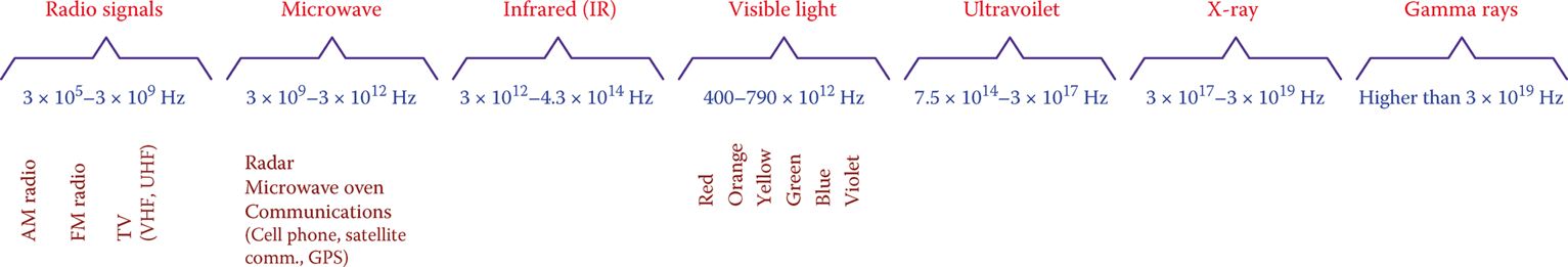
Figure 1 General electromagnetic wave spectrum.
At industrial and commercial levels, to be efficient and cost-effective, the electrical power to be transmitted from one point to another must be in megawatts. Because energy from the sun is at low grade (meaning only a small amount of energy per square foot or square meter per second), a large area of coverage is needed.
Also, it is obvious that solar energy is available only during the daytime and, moreover, this energy is subject to the weather condition as well as the time of the day.
The average power from the sun outside the Earth’s atmosphere is about 1365 W/m2 (127.0 W/ft2). This is called solar irradiance, which is, indeed, the rate of available solar energy before reaching the Earth’s surface.
To determine the available energy in any length of time, which can also be converted to calories or any other unit, the solar irradiance must be multiplied by the time duration. For instance, the available energy in 1 hour (3600 s) is 4914 kJ/m2 per hour or 1174.2 kcal/m2 per hour (457 kJ/ft2 or approximately 433 BTU/ft2 per hour).
Solar irradiance: Rate of available solar energy on Earth per square meter (or per square foot). It is, thus, measured in W/m2, or W/ft2.
This energy, however, is decreased when arriving at the Earth’s surface owing to various reasons, mostly clouds and particles in the air and partly because of reflection and absorption (air, water vapor, and air pollutants in the air absorb heat and become warmer. They also reflect part of the sun rays back to the atmosphere.) On a very clear day, up to 30 percent of the solar energy can be lost this way. This loss can reach 90 percent for a cloudy day.
Despite the fact that a great percentage of the energy from the sun can be reduced by the atmosphere, total energy reaching the Earth’s surface is tremendous because of the available area.
A study by the US Department of Energy has shown that the total US electrical energy consumption (3.24 TW = 3.24 × 10¹² W) could be provided by the sun if the energy from the sun is collected in an area approximately the size of North Dakota or South Dakota.
Out of the tremendous amount of energy from the sun reaching the Earth, a good percentage is lost in the atmosphere owing to clouds and air pollution.
Photovoltaic Systems
Photovoltaic systems are based on the reaction of certain semiconductor materials to light. A solar cell is the smallest unit in a photovoltaic panel that, on the basis of its material, is sensitive to one or more of the rays in the sunlight spectrum. A small voltage is generated by a solar cell depending on the sensitivity of the material and the intensity of the light.
A solar cell is, in fact, a diode with a function opposite to that of an LED; thus, it generates a voltage when subjected to light. Figure 2 shows the symbol for a photovoltaic cell.
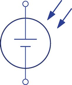
Figure 2 Symbol for a photovoltaic cell.
Solar cell: Semiconductor diode that converts light to voltage (the opposite of what an LED does).
A solar cell can be regarded as a small battery. The voltage of this battery is small, between 0.5 and 1 V, depending on the material used for the cell construction. In this respect, to obtain a higher voltage, a number of cells must be joined together in series, like inside a car battery.
Moreover, current that can be delivered by an individual solar cell is small, on the order of milliamps. For this reason, the cells must be put in parallel with each other so as to deliver more current.
Consequently, to use solar energy at the desired voltage and capable of delivering the desired power, a number of solar cells are put together in rows and columns in a solar panel, which is a unit that can be practically and physically meaningful to handle. Then, many solar panels can be put together, again in rows and columns, in a solar array to provide higher voltage and higher current.
Solar panel: Set of solar cells put together in a frame and connected together in series, parallel combination to deliver a desired voltage at the desired current.
Solar array: Set of solar panels put together in the form of a matrix (rows and columns) and connected together in series, parallel, or a combination to deliver a desired voltage at the desired current.
The current that a typical solar cell can deliver is not constant and depends on the voltage at which this current is delivered. In other words, a solar cell works based on its characteristic curve that delineates the relationship between its current and voltage.
Figure 3 depicts the form of a typical curve for all solar cells. The voltage is shown on the horizontal axis and the current on the vertical axis.
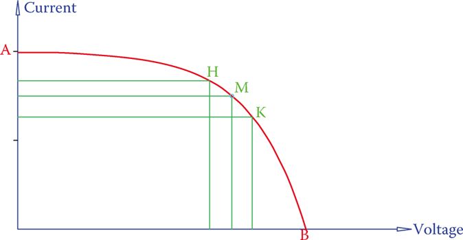
Figure 3 Typical I-V curve for the performance of a solar cell.
As can be seen, current drops abruptly when the cell voltage approaches its maximum value for a given type of cell. In the graph, point A corresponds to zero voltage and highest current (short circuit of the cell) and point B corresponds to zero current and highest voltage (open circuit).
Because power is the product of current and voltage, at both these points (A and B), the power output of a cell is zero. This implies that a solar cell (and correspondingly solar panels) cannot be used at these extreme points.
For any point on the curve, the deliverable power is represented by the area of a rectangle formed from that point being a corner. This is shown for two arbitrary points H and K in Figure 3. For a point M, this deliverable power by a cell is the highest.
Thus, to use a solar panel at its maximum power (in other words for gaining the maximum power from sunlight), the operating point of a solar panel must be around point M.
Obviously, the I-V curve (characteristic curve), and consequently the point of maximum power, of a solar cell cannot be invariable, because this depends on the intensity of light. If such a curve is drawn for various light conditions, a series of curves have obtained that look like those shown in Figure 4.
Under different light conditions, the variation of the maximum (open circuit) voltage VOC (point B) is less affected, but the deliverable maximum current ISC (point A) has significant displacement. The position of the point of maximum power (point M) also moves.
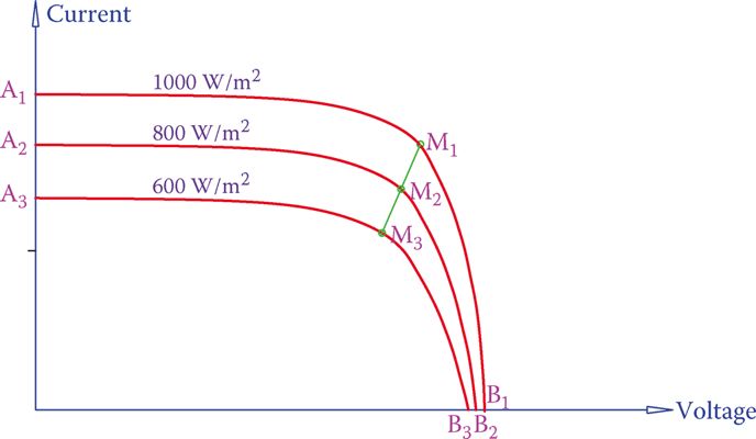
Figure 4 Set of I-V characteristic curves for a solar cell under different light conditions.
To compare the performance of two solar cells under similar conditions, the term fill factor is employed.
Fill factor is a percentage value, obtained by the ratio of the maximum power possible from a solar cell to the product of the open circuit voltage and short circuit current. This product is shown by the area of the rectangle in Figure 5 for two cells that have the same values for VOC and ISC. Observation of this figure depicts that the solar cell with the characteristic curve AM2B produces more power than that with the curve AM1B.
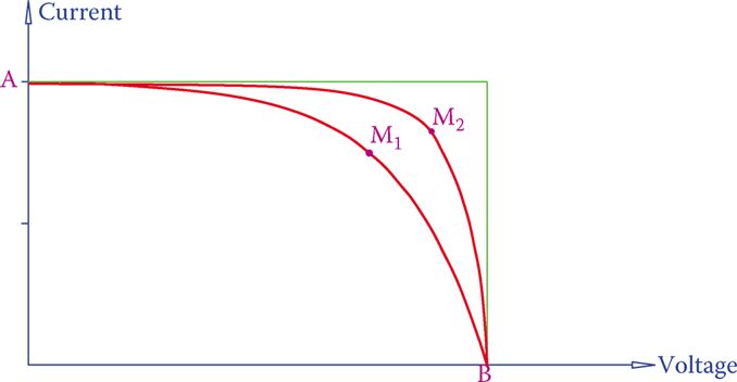
Figure 5 Representation of the fill factor concept.
Fill factor: Ratio of the maximum power possible from a solar cell to the product of its maximum voltage and maximum current (i.e., the product of the open circuit voltage and the short circuit current).
Also, to have a common criterion for comparing various PV cells, it is customary to plot these curves for a standard condition defined by an irradiation of 1000 W/m2 (93 W/ft2) and at 25°C (77°F).
The reason to involve the temperature is the fact that the performance of PV cells is not independent of the operating temperature. The performance of a PV cell deteriorates (and as a result, the characteristic curve alters) as the temperature increases. This change mostly affects the maximum voltage (and the maximum power, as a result).
Figure 6 illustrates the typical change for the I-V curve. The short circuit current does not remain the same, but its change is negligible.
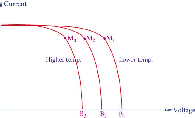
Figure 6 Effect of temperature on I-V characteristics of a solar cell.
Another measure for comparing different units of solar panels is their efficiency. Efficiency is always the ratio of output power to the input power, and it is expressed in percentage.
For a PV unit, efficiency can be defined as the ratio of the maximum power to the product of cell area and irradiance. Table 1 shows the voltages and other information for some solar cells made from different materials.
Table 1: Specifications of Some Solar Cells
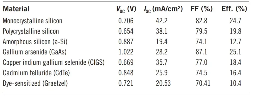
Fill factor can be used for comparison of two different types of solar cells. Efficiency can be used to evaluate the performance of a solar array or a solar farm.
For an installed PV system consisting of a large number of solar arrays it often becomes necessary to evaluate the efficiency of the system for financial matters. The same formulation for the efficiency of a single unit can be extended for this purpose.
The real efficiency for this system, however, can be lower than the theoretical efficiency because the panels may not always work at their maximum power condition. Furthermore, some units can be faulty or damaged.
The solar cell area is always known for the number of units in use. The average irradiance for a region can always be found based on statistics of weather conditions. The average power output may be found based on the data from production.
- You May Also Read: Solar Hot Water System: Working Principle & Types
Residential Solar Heating System
The heat from the sun can be directly used for heating space or water in a building, at a small scale, or it can be collected and concentrated to run industrial size steam turbines for generation of electricity, at a large scale.
Heating water in a residential building is the simplest case of using solar energy. In such a system, water moves through a number of pipes that are placed on the roof of a building and absorb the heat directly from the sunshine. For maximum performance, these pipes, called collectors, are black colored.
The heated water can be moved to a tank by natural convection or by assistance from a pump. For natural convection, the reservoir tank must be physically higher than the position of the collector pipes because warm water moves up. In this way, water continuously circulates between the tank and the collector. At each circulation, it gets warmer. The warmed water can be used and replaced by fresh cold water, as shown in Figure 7.
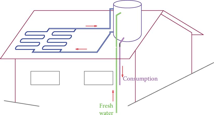
Figure 7 Example of solar heating in a residential building.
If the reservoir is not at a higher level than the collectors, a pump is needed to circulate the water to warm up. For this application, the size of collectors can be determined for each individual case based on available sunshine, desired temperature, and water consumption.
The above arrangement can also be used for space heating. Instead of consuming the heated water, it can be circulated in radiators inside a building. A reservoir tank always helps to store the heat and smooth the heat flow, just as a capacitor does for electricity, but in particular cases, it can be omitted.
Industrial Solar Heating System
Another way that solar energy can be used for space heating at a small scale is shown in Figure 8. This approach has been practiced in special cases in manufacturing and process plants in which the air inside the building must be continuously replaced by fresh air owing to fumes or other reasons. For this, blowers must suck the fresh air from outside, heat it, and send it to the inside of a building.
In this arrangement, a black glass wall just in front of the main wall on the sunny side of the building absorbs heat from the sun and heats the air between the glass wall and the structural wall of the building. Holes on the top of the wall let the heated air enter the building. Blowers can help as necessary and the temperature can be adjusted by auxiliary heating when required.
If a good candidate for this arrangement, an industrial building can save hundreds of thousands of dollars in a year, for instance, on heating costs.
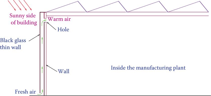
Figure 8 Way of utilizing solar heating in an industrial building.
Solar heating at large scale (megawatts of power) is more involved. This is like a power plant with a steam turbine except that instead of gas or coal heating of water and generation of steam must be done through the energy from the sun.
In an ordinary steam turbine power plant, water temperature is raised in a boiler for conversion to steam. It is technically necessary, as well as more efficient, that only superheated steam enters a turbine. Thus, steam is further heated to increase its temperature and pressure. This requires temperatures somewhat higher than the boiling temperature for water (unless some other substance is used, which introduces its own technical concerns and adds some other complexities).
To duplicate the same process of producing superheated steam, the solar energy is concentrated by a great number of collectors, consisting of concave mirrors that must reflect their absorbed heat to a common point. For better performance, moreover, these mirrors must track the position of the sun during the daytime.