The synchronous motor, like all other rotating motors, has a stator and a rotor. Figure 1 shows a cutaway view of a synchronous motor. The rotor contains electromagnets, which create the field of the motor. In some cases, permanent magnets are used on the rotor of a synchronous machine to create the field.
The motor in Figure 1 has electromagnets on the rotor so a DC source is required to provide power to the coils. The DC source and its associated controls are referred to as the excitation system.
The motor in Figure 1 has a second motor mounted on its shaft to provide the excitation. The stator of the motor contains the armature coil, which is the high-power AC winding. Each of these components will be described in some detail in this section.
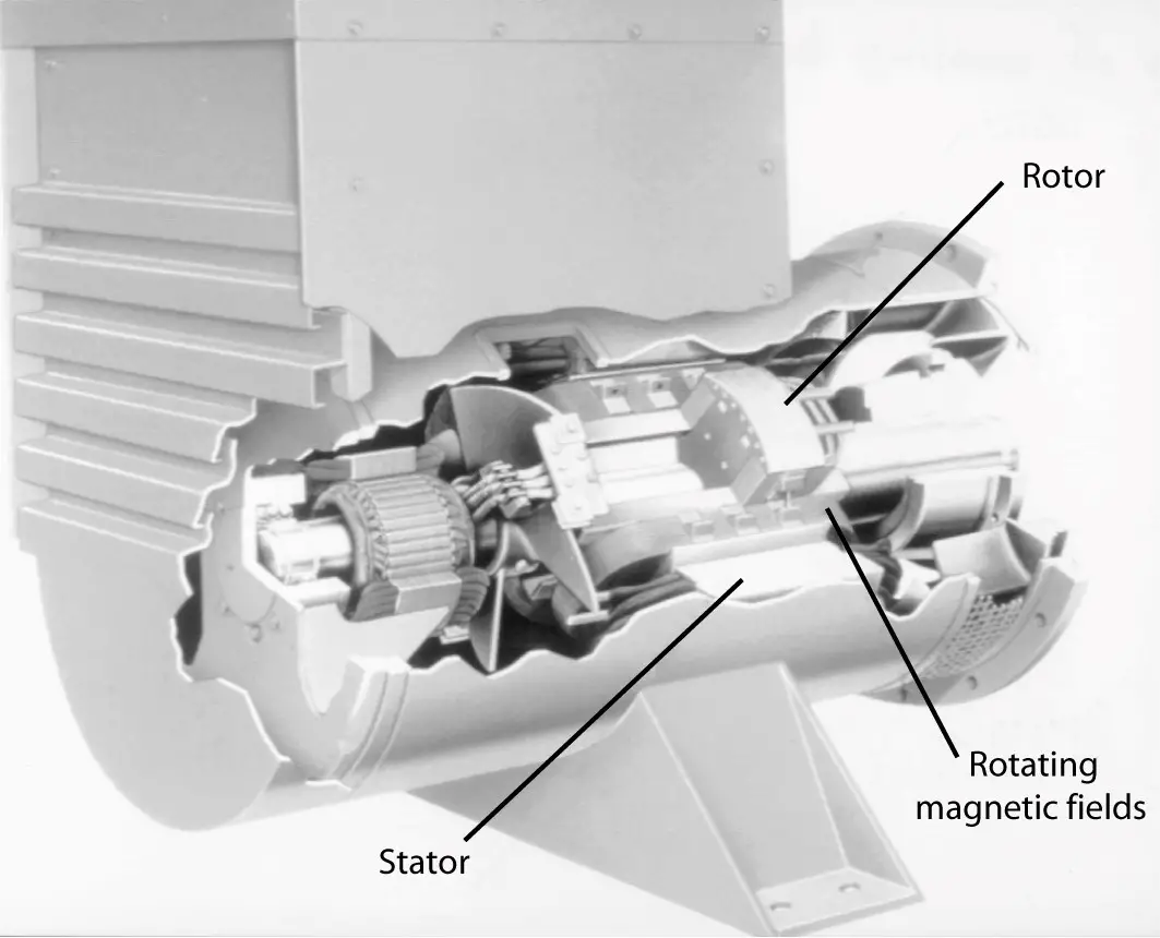
FIGURE 1: Cutaway view of a synchronous motor. (Courtesy of Caterpillar Inc.)
The stator and armature winding
The armature winding is identical to the stator winding of an induction motor. Since the armature is an AC winding, the steel core of the stator is built of laminations.
Figure 2 shows a stator core for an intermediate-size synchronous machine. The windings for the three phases are placed in the slots of the stator core such that the phases are 120° apart.
Several types of windings are used, depending on the size of the motor. Small- and intermediate-size motors use wound coils; large motors use bar-type conductors that are laid into the slots.
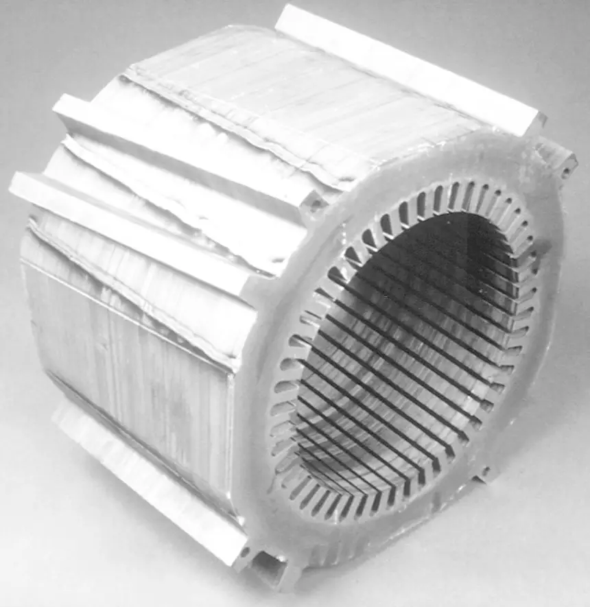
FIGURE 2: Stator core of a synchronous motor. (Courtesy of Caterpillar Inc.)
Figure 3 shows two types of wound coils. The top coil is a random-wound or mush coil. Magnet wire is wound into a multi-turn coil or set of coils that is then stuffed into the slots of the stator core.
The lower coil in Figure 3 is a form- type coil. As the name implies, it is wound on a form with a very specific shape. When the coils are laid into the slots of the stator, the shaping allows them to go up and over the next coil in the winding.
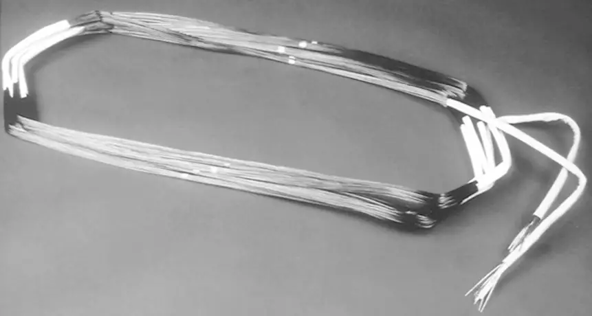
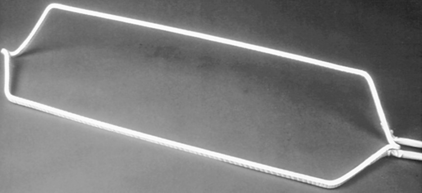
FIGURE 3: Wound armature coils. (Courtesy of Caterpillar Inc.)
The rotor and field winding
There are two types of rotors, cylindrical and salient pole. The number of poles is limited by the complexity of putting the winding on the rotor. Because there are only two or four poles, the round rotor runs at high speed, which causes higher centripetal forces on the windings. To keep the windings from being thrown out of their slots, round rotors are usually long and thin (small diameter). For slower-speed motors, salient-pole rotors are used.
Salient-pole rotors have very identifiable pole-faces behind which are mounted the field coils. Figures 4 through 9 show pictures of salient rotors and parts of salient rotors. Figure 4 is a picture of a six-pole, salient-pole rotor. The pole-faces form north and south poles due to the coils that are mounted behind them. This particular rotor has removable pole assemblies.
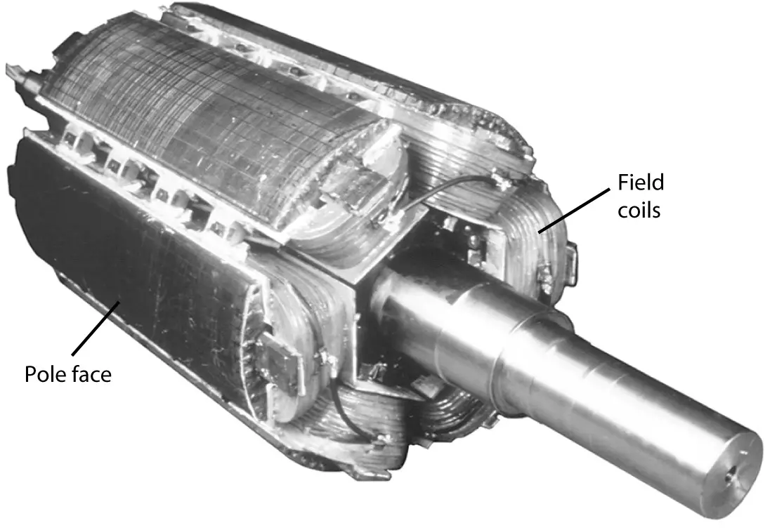
FIGURE 4: Six-pole, salient-pole synchronous motor rotor. (Courtesy of Caterpillar Inc.)
Figure 5 shows the top view of a pole-face without a rotor coil, and Figure 6 shows a bot tom view of a field coil mounted on the pole-face. Not all salient-pole rotors have removable pole assemblies; however, on some motors, the rotor assembly is built of laminations and the coils are forced on around the pole-face.
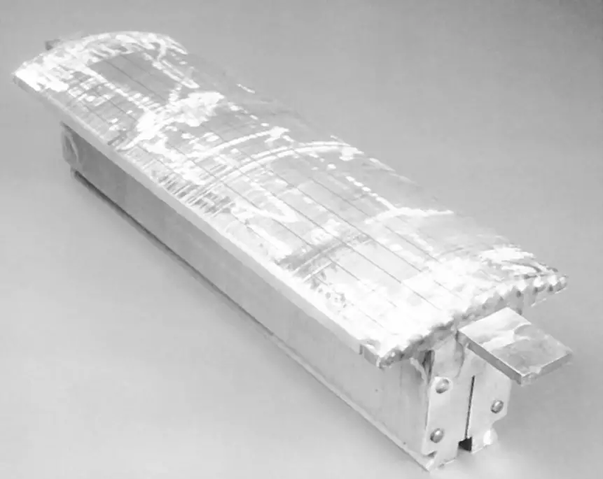
FIGURE 5: Top view of pole piece without coil for the rotor of Figure 4. (Courtesy of Caterpillar Inc.)
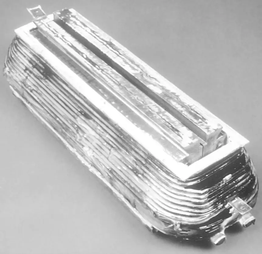
FIGURE 6: Bottom view of pole piece with the coil for the rotor of Figure 4. (Courtesy of Caterpillar Inc.)
Figure 7 shows a salient pole rotor that is constructed of laminations of electrical steel, such as the one shown in Figure 8. The pins that protrude from the ends of the poles in Figure 7 are there to hold the held coils in place when the rotor is revolving. All of these rotors require a source of DC power to create the field flux from the rotor pole-faces.
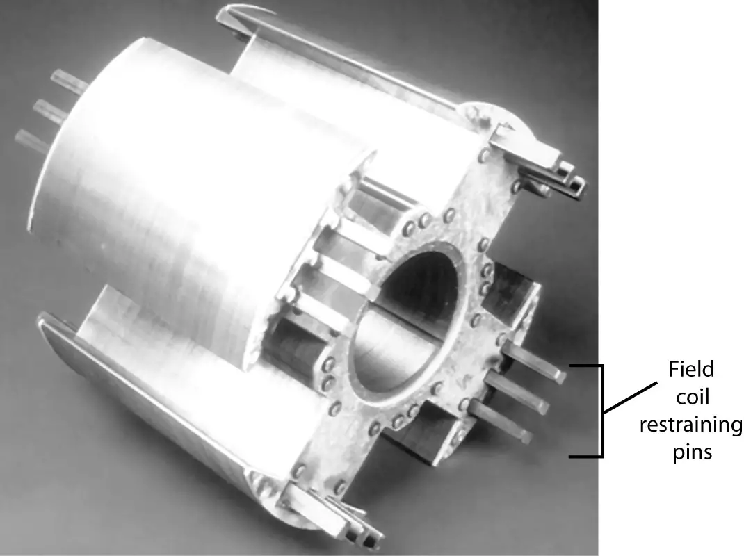
FIGURE 7: Four-pole, salient-pole synchronous motor rotor without field windings. (Courtesy of Caterpillar Inc.)
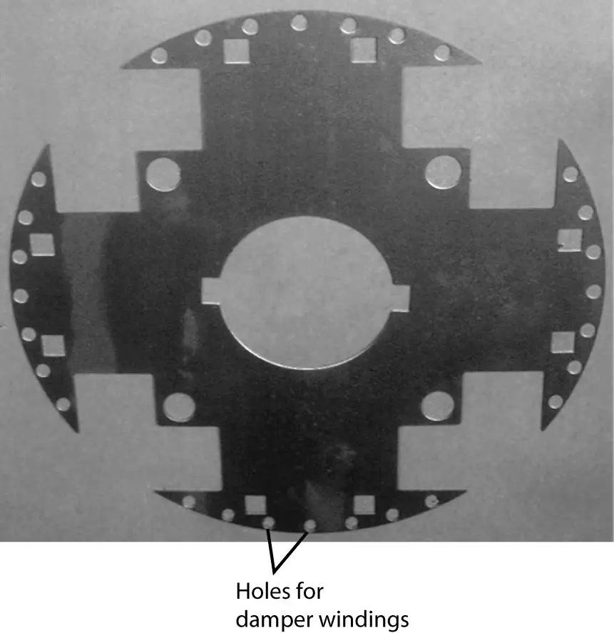
FIGURE 8: Lamination of the rotor of Figure 7. (Courtesy of Caterpillar Inc.)
Excitation of a Synchronous Motor
There are several ways to provide DC to the rotor winding. In the past, slip rings and brushes were always used to make the connection to the field winding. In these cases, DC power may be provided from an external DC generator, a rectifier, or from a DC generator mounted on the same shaft as the synchronous motor. Today, however, it is possible to use an AC generator mounted on the same shaft.
The exciter generator is built “inside-out” with a stationary field and a rotating armature. The AC output of the armature is rectified to DC using power electronic devices that are also mounted on the shaft. In this case, the DC can be fed directly to the field without slip rings. Hence, this is called brushless excitation.
Figure 9 shows a rotor assembly from a synchronous motor that uses brushless excitation. On the left side of the rotor, we see four salient poles with the held coils mounted behind them, while on the right side of the rotor, we note a smaller AC armature. The exciter also requires excitation, which can be provided by permanent magnets or a smaller DC power supply. The rotating rectifiers are mounted on the rotor between the field windings and the exciter armature.
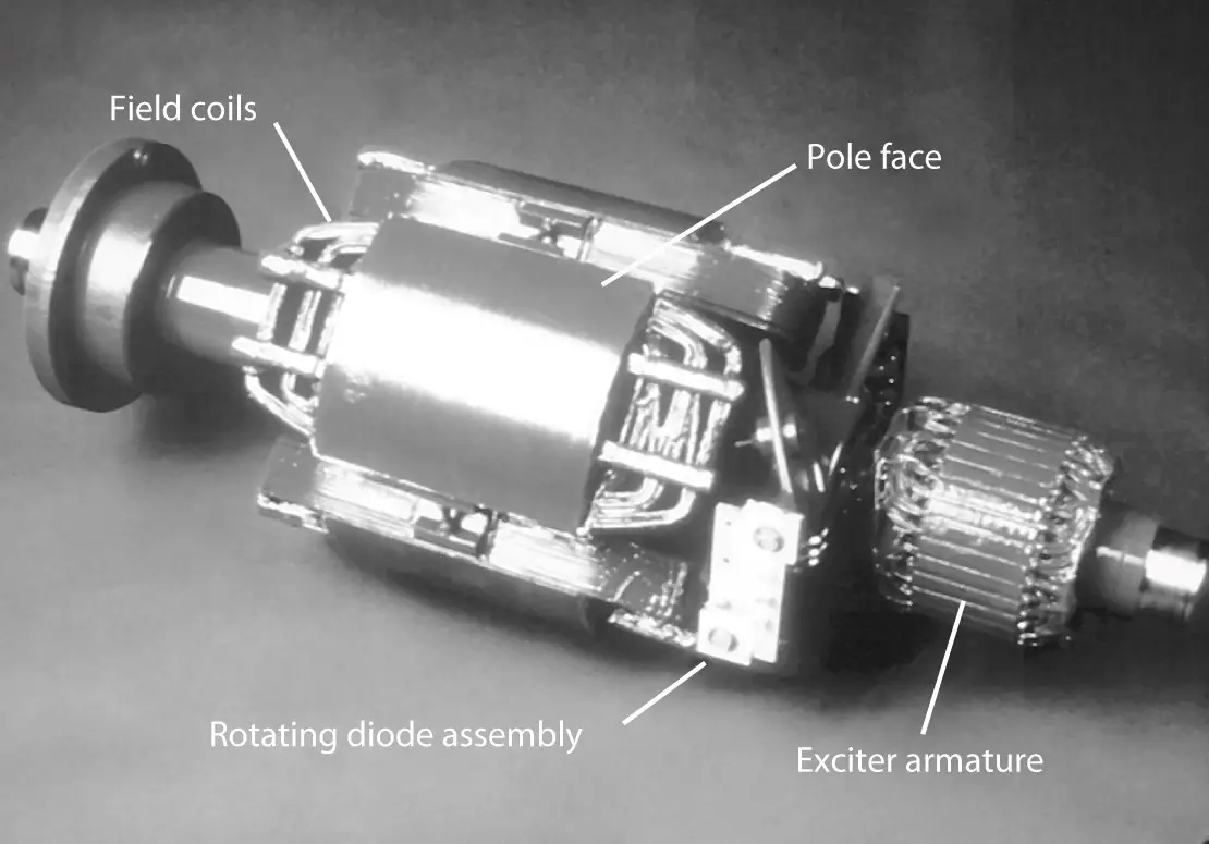
FIGURE 9: a Synchronous motor rotor with brushless exciter system. (Courtesy of Caterpillar Inc.)