The losses in a synchronous machine affect its cost, rating, and performance. The efficiency of a synchronous machine is frequently determined by measuring the losses, using techniques that are precisely defined by ANSI, IEEE, and NEMA measurement standards.
The efficiency is defined in the same way as it is for transformers and other types of machines:
\[\begin{matrix} \text{ }\!\!\eta\!\!\text{ =}\frac{\text{Output Power}}{\text{Input Power}} & {} & {} \\ \text{ }\!\!\eta\!\!\text{ =}\frac{\text{Input Power-Losses}}{\text{Input Power}} & {} & \left( \text{1} \right) \\ \text{ }\!\!\eta\!\!\text{ =}\frac{\text{Output Power}}{\text{Output Power+Losses}} & {} & {} \\\end{matrix}\]
Ratings and Heating of Synchronous Machines
One of the most important factors in selecting a motor or generator is its maximum continuous output power. The machine’s power rating depends primarily on its allowable operating temperature and how fast it can dissipate the heat that results from the losses in the machine.
The machine must meet performance standards, and its life must not be reduced by overheating when operating at its rated power. The machine rating is always the output of the machine (shaft horsepower for a motor and output kW for a generator).
Figures 1 and 2 show the power flow through a synchronous generator and motor, respectively. In each case, the power of one form is input to the machine and losses are subtracted one by one until the output side.
Unlike the induction motor, the synchronous machine also has power input to the field windings. The power flow diagrams are discussed in more detail below, but first, we will consider the losses in the synchronous machine.
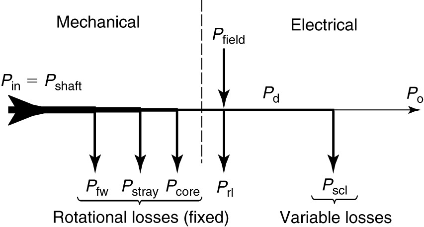
FIGURE 1: Power flow for a synchronous generator.
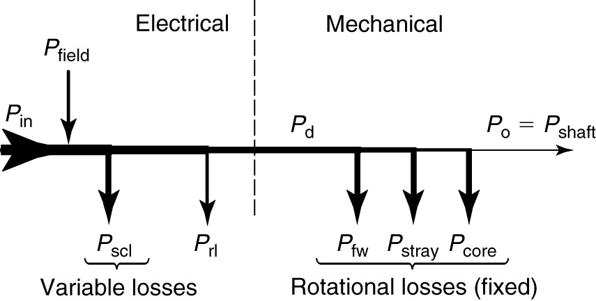
FIGURE 2: Power flow for a synchronous motor.
Types of Losses in Synchronous Machines
The losses in the synchronous machine are similar to those of the transformer and other types of rotating machines. Like all electrical machines, synchronous machines have copper, steel, rotational, and stray losses. Whether the machine operates as a motor or as a generator, the losses can be summed as
$\begin{matrix} {{P}_{loss}}={{P}_{scl}}+{{P}_{rl}}+{{P}_{fw}}+{{P}_{core}}+{{P}_{stray}} & {} & \left( 2 \right) \\\end{matrix}$
Where
Pscl = the copper loss in the stator (armature) windings
Pri = losses in the rotor, which includes the copper losses of the field windings, the losses in the excitation system, and copper losses in the damper windings
Pfw = friction and windage losses
Pcore = hysteresis and eddy current losses, primarily in the stator iron
Pstray = stray losses not otherwise accounted for in the calculation of the other losses
Copper Losses
Copper losses are found in all the windings in the machine. By convention, they are computed using the DC resistance of the winding at 75°C. The actual resistance depends on the operating frequency and flux conditions. Any difference between the actual and computed copper loss is accounted for under the stray loss category. Brush losses for machines with slip rings are normally neglected and accounted for under the stray loss category.
Mechanical Losses
The mechanical or friction and windage losses are due to the friction in the bearings and the energy that is dissipated in turning the rotor through the air inside the machine.
The rotational losses can be determined by driving the machine at rated speed with no load or excitation. Rotational losses are frequently lumped with core loss and determined at the same time.
Open-Circuit or No-Load Core Losses
The core loss due to hysteresis and eddy currents is measured at no load, and when combined with the mechanical losses, they constitute the no-load rotational loss. The difference between the measured and actual core loss is put in the stray loss category.
Stray Loss
Stray losses include the difference between the actual losses and their calculated values, as well as losses that are not specifically calculated, such as the brush contact loss.
Power Flow in Machines
Generator Power Flow
The synchronous generator has two power inputs, mechanical power at the shaft and electrical power to the field, and one output, electrical power to a load. As shown in Figure 1, mechanical power is input at the left side of the diagram.
Rotational losses are mechanical in nature and are thus subtracted from the mechanical power. This includes not only friction and windage but, by convention, stray losses and core losses also.
The power input to the field and the rotor losses are shown at the center. These two quantities essentially cancel each other. The remaining power is transformed into electrical power, and this quantity is called the developed power. In the case of a three-phase synchronous generator, the developed power is
\[\begin{matrix} {{P}_{d}}=3{{E}_{a}}{{I}_{L}}\cos \left( \theta +\delta \right) & {} & \left( 3 \right) \\\end{matrix}\]
Where Ea is a line-to-neutral voltage.
Thus, the power in the controlled voltage source of the equivalent circuit represents the developed power. From the developed power, we subtract the copper losses in the machine windings to obtain the output power of the generator.
Motor Power Flow
Motors receive electrical power at the armature as their inputs and deliver mechanical power at the shaft of the machine. For the power flow diagram, shown in Figure 2, the electrical power is input at the left. The copper losses are subtracted, leaving the developed power in the middle.
The developed power is represented in the equivalent circuit of the synchronous motor by the power in the controlled voltage source and is calculated from equation 3. From the developed power, we subtract the friction and windage, core, and stray losses to find the output mechanical power.