With long-distance transmission lines the characteristics of the line affect the voltage at the delivery end of the line. The conductors have an inherent capacitance between them and there is an inductive effect due to the length of the parallel conductors. Each conductor also has a fixed value of resistance.
At light loads with little or no current flow, resistance and inductance are not a problem; the capacitance effect between lines is the dominant characteristic. The result is a leading power factor on the line and a delivery voltage that might be higher than the source voltage.
With heavily loaded lines, the voltage drop due to the line resistance and inductance increases in proportion to the current. While the line capacitance effect still remains constant, there is now a magnetic coupling effect due to the magnetic field surrounding the conductors. The inductive effect increases and so does the voltage drop. These effects result in a reduced voltage at the load end of the line and at a lagging power factor.
Synchronous capacitors can be used to correct the power factor and so correct the line voltage, but the more usual and cheaper way is to vary the line voltage with transformer tap changers at the source of the supply.
Tap changers are installed in situations where they can compensate for variations in voltage. A rising or falling voltage at the load end of the line can be corrected by the action of a tap changer at the supply end. There are two possible ways of doing this—off load and on load.
Off-Load Tap Changing
The off-load tap-changing method merely involves disconnecting the transformer from the supply, adjusting the turns ratio, and then reconnecting the transformer to the supply. The tap changing can be done only after disconnecting the transformer from the supply.
To facilitate the changeover, there are usually built-in switches and the task only involves turning a handle or operating a lever. It always causes an interruption to the supply, unless there is a second transformer available, which must be connected to the supply before the first one is removed.
On-Load Tap Changing
When it is necessary that a transformer provide a constant voltage into a supply system, a means must be found to alter the transformer ratio while the transformer is still on line, so ensuring that there is no interruption to the supply.
On-load tap changing is more convenient to consumers and suppliers alike and the procedure lends itself to automatic operation so that line voltages can be regulated without manual intervention.
On-load tap changing is illustrated in Figure 1 for only one phase. In a three-phase power system there must obviously be three such systems, all operating simultaneously.
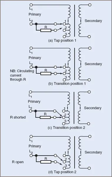
Figure 1 On-Load Tap Changing Transformer Diagram
For clarity, the primary winding is shown in two sections. Three taps only are shown at the other end of the primary winding and the selected transformer tap is connected to the other line through a dual switching mechanism.
In Figure 1(a), one of the supply lines is connected to tap 1. The other part of the switching mechanism is open circuit.
In Figure 1(b), tap changing has been initiated. The second part of the switch has connected the low value resistor R to tap 2. The potential difference between taps 1 and 2 causes a circulating current to flow through the resistor.
In Figure 1(c), the switching mechanism has been connected to tap 2. Resistor R has been shorted out.
In Figure 1(d), the resistor R has again been isolated by the switching mechanism. The supply to the transmission lines has not been interrupted, yet the input to the transformer has been shifted to another tap.
Resistor tap changers are lighter, cheaper and more compact than the previously used center-tapped inductor changeover mechanisms. The transition process takes only a few cycles and is commenced by releasing the energy stored in a spring under tension.