It is sometimes necessary to operate two or more transformers in parallel and to do so, not only must the output voltages be equal but the instantaneous polarities must be the same.
Single-Phase Transformers
Equal voltages
When two unequal voltage sources are connected in parallel, the phasor difference between the voltages causes a circulating current to be set up. The current flow is limited only by the impedances of the windings and will flow despite all other conditions for parallel operation being met.
Large quantities of heat are generated and the circulating current effectively renders both sources of power useless for any practical purposes.
Instantaneous Polarities
The two transformers shown in Figure 1 have their primary windings wound in the same direction around the iron core. When the instantaneous polarity of line A is positive (indicated by the dot), the mutual flux Φ in each transformer acts in the same direction.
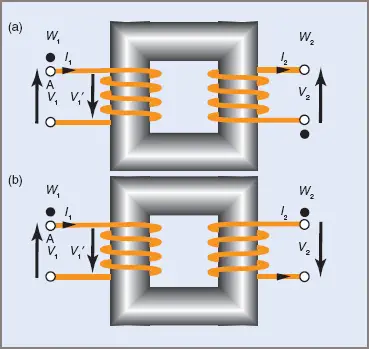
Figure 1 Winding Polarity
The secondary windings in Figure 1 are shown wound in opposite directions to each other. The induced voltage V2 acts in an upward direction in (a), while in (b) V2 acts downward. In both cases the secondary flux Φ2 must oppose the mutual flux (Lenz’s law). This condition is met by the induced voltage acting downward in (b) and producing an instantaneous current flow as indicated by the arrows in both figures. That is, when an instantaneously positive voltage is applied to the primary terminals indicated by the dots, there will be an instantaneously positive voltage produced at the secondary terminals indicated by dots. In general terms the positioning of dots on winding ends is used to indicate the similar instantaneous polarities.
For single-phase transformers to operate in parallel, their voltages must be equal and their instantaneous polarities must also be identical.
The correct connections for two transformers in parallel are shown in Figure 2.
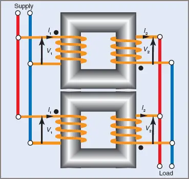
Figure 2 Parallel Transformers Connection
If terminals of the wrong polarity are connected together, a high circulating current is set up in both primary and secondary windings. Effectively the two secondary windings are connected in series and then short-circuited. The path for the circulating current is shown in Figure 3 as a thicker line.
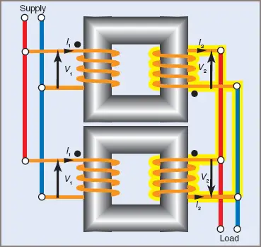
Figure 3 Path for Circular Current in Transformer
Terminal Polarity Identification—Single Phase
When drawing sketches of transformers, the dot or a similar system of identification for winding ends is satisfactory. In practice it is more usual to be confronted with a transformer and a row of terminals, making some general system of identification necessary.
Australian Standard AS/NZS 2374 sets out such a system for power transformers. In brief, all terminals are given an identifying letter and a subscript number—for the higher voltage winding capital letters are used, and for the lower voltage winding lower-case letters are used.
Where more than one end of a winding is brought out to a terminal, the higher number is the line terminal unless a specific phase shift is required.
An example for a single-phase transformer is shown in Figure 4. The standard specifies that the identification be permanently marked on, or adjacent to, the terminals. Invariably this means stamping the identification into the metal of the terminal or the case adjacent to the terminal.
In addition to this marking, supply authorities might require further markings on the transformer to assist them in installation or to match their phase sequence.
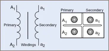
Figure 4 Typical terminal arrangements for a single-phase transformers
- You May Also Read: Transformer Polarity Test
Three-Phase Transformers
A transformer can be used on a three-phase supply by using a three-legged core with primary and secondary windings on each leg, as shown in Figure 5. The fluxes established in the windings are 120°E apart and their instantaneous sum will always be zero.
Two of the fluxes will flow back through the third leg, in the same way that the resultant current in any two lines of a three-phase system will flow back through the third line.
Because the three windings are on a common core, the three-phase transformer is smaller and lighter than three separate transformers for the same VA rating.
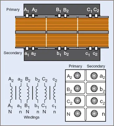
Figure 5 Typical terminal arrangements for a star–star transformer with three-phase Australian Standard 2374 markings
Terminal Polarity Identification—Three Phase
Standard AS/NZS 2374 sets out the same terminal arrangement and identification for both single- and three-phase transformers. There is now a greater variety of alternative connections available, so the system is necessarily more complicated than that for single-phase transformers.
Capital letters with numerical subscripts are used for the higher voltage winding, with lower case for the lower voltage winding. The standard terminal arrangement is also shown for the transformer.
AS/NZS 2374 states that the terminal arrangement shall be in the order A, B, C from left to right when looking from the high-voltage side. When a neutral is fitted, its terminal shall be on the extreme left-hand side.
It should be noted that supply authorities do not necessarily follow this standard. One supply authority uses the sequence b2, n, c2, a2 in one situation and the sequence a2, n, b2, c2 in another. There are valid reasons for persisting with a non-standard order and these vary from one authority to another.