Consider the simple model of the atom in Figure 1. Electrons move around the nucleus like the earth around the sun. This electron motion is a small electric current, and anywhere there is a current, there is a magnetic field (moment). Electrons also spin around their axes like the earth.
If the electron charge is considered to be distributed on the surface of the electron, the spinning creates another current and an additional magnetic moment. For about two-thirds of the elements, the orbital and spin moments cancel, so the atom has no net moment. Furthermore, in all but five of the remaining elements, the neighboring atoms cancel each other, and there is no net moment in the material.
There are five elements that have a net magnetic moment—two are the rare earth that are sometimes used in permanent magnets, and the other three are iron, nickel, and cobalt (including their alloys and oxides). These materials are called ferromagnetic.
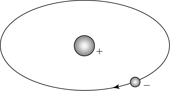
FIGURE 1 Simple model of an atom.
Ferromagnetic Materials
Metals are crystalline in structure. The metallic crystals contain microscopic magnetic domains, an illustration of which is shown in Figure 2.
Domains tend to align along axes of easy magnetization. When the material is initially formed and there is no applied field, the domains are randomly oriented and cancel so there is no net moment, as shown in Figure 2(a).
When we apply an MMF to the material, domains in the direction of the applied magnetic field tend to expand and some may rotate. This is shown in Figure 2(b), where the wide arrows indicate the domain has aligned its flux with the external field. As more of the domains align with the external field, they effectively magnify the field.

FIGURE 2 Magnetic domains in a ferromagnetic material.
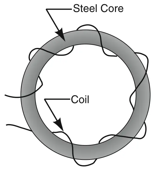
FIGURE 3 Toroidal inductor.
Consider the cast steel toroid with a coil shown in Figure 3. Applying a current (MMF) results in a magnetic field in the core. We can consider it as B = Bo + M, where Bo is the flux density that would exist without an iron core and M is the contribution of the iron.

FIGURE 4 Magnetic characteristic.
Figure 4 shows a plot of B versus H (= NI/l). Initially, the applied field intensity is not strong enough to change the domains, and they don’t contribute much to the flux density. This is region 1 in Figure 4. Thus, the relative permeability is low. As the current, and thus H, are increased to higher values, domains expand and rotate quickly, and µr may be very high. This is region 2 in Figure 4.

FIGURE 5 B-H curve for three different materials.
Finally, we reach a point where all the easy domains are aligned, and the relative permeability begins to drop again. This is indicated by region 3, which is called the saturation region of the curve.
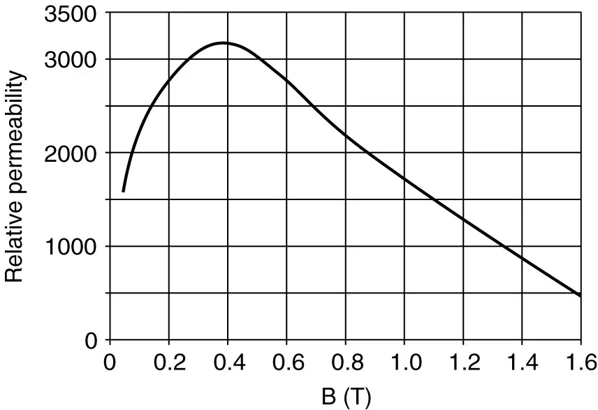
FIGURE 6 Relative permeability of sheet steel.
Some ferromagnetic materials have a higher relative permeability than other materials and are easier to magnetize. Figure 5 shows B-H curves for cast iron, cast steel, and sheet steel. Thus, materials with the same name may be magnetically different. This is particularly true for sheet steel. Electrical steel makers usually produce many different types of steel, each with specific characteristics. We can calculate the relative permeability of a material as a function of flux density using B = µo µr H. Therefore,
\[\begin{matrix} {{\mu }_{r}}=\frac{B}{{{\mu }_{o}}H} & {} & \left( 1 \right) \\\end{matrix}\]
Figure 6 shows the relative permeability of sheet steel as a function of the flux density. These values were calculated using data from Figure 5. Because the permeability of ferromagnetic materials is variable, the reluctance of any magnetic circuit containing ferromagnetic material is also variable.