
Figure 1. Digital Multimeter Labeled Diagram
How Digital Multimeter Works?
A digital multimeter (DMM) is a multifunctional meter that displays its electrical quantitative values on an LCD screen. A digital multimeter much like an analog meter, it is able to read voltage, current, and resistance. What makes a digital multimeter differ from the analog meter is its ability to display measured electrical values quickly without any computations. Because of its design, a processor can be built into the meter which allows the user to take measurements of frequency, the inductance of a coil, capacitance of a capacitor, and a host of other high functional electrical measurements.
There two types of digital multimeters (DMM): scalable digital multimeter and auto-ranging digital multimeter as shown in Figure 1. When working with the scalable digital multimeter you need to have an idea of the value of voltage, current, or resistance that you are attempting to measure. Failure to observe these values will result in inaccurate readings and possible damage to the meter. The auto-ranging digital multimeter is more widely used due to its ease, high functionality, and quick display readings achieved without the user completing the calculations.
- You May Also Read: Digital Ammeter Working Principle
Digital Multimeter Block Diagram
The following Figure 2 represents the digital multimeter block diagram with all the functional blocks.

Figure 2. Digital Multimeter Block Diagram
The auto-ranging digital multimeter (DMM) only requires you to select the electrical quantity you want to measure, make sure the leads are correctly placed in the appropriate terminals, and then read the value on the LCD display. Auto-ranging digital multimeters allow technicians to spend more time getting to the root of a problem instead of switching and calculating.
- You May Also Read: Digital Frequency Meter Working Principle
Step by Step Guide on How to Use a Digital Multimeter to Test for Voltage
Testing for voltage is carried out to ensure the effectiveness of the electrical system. Loads (for example lights or motors) that are designed to do the work need a nominal voltage to operate. Overvoltage will result in equipment failure and not enough voltage will result in the load not turn on. When testing voltage there is an expected voltage reading to look for. If the load is rated at 120 volts then the expected reading from the outlet needs to be 120 volts plus or minus 10%. If the voltage reading is out of specifications then the problem can be found using the voltmeter to isolate the load and find if there is a problem with the source or the load.
Here is a step by step guide on how to use a multimeter to test for voltage:
- First, figure out whether the application being testing utilizes AC or DC voltage. Afterward, adjust the meter dial to the suitable function to DC Voltage or AC voltage.
- Adjust the range to the number little higher than the predictive value. If the value being measured is unknown, then set the range to the maximum available number.
- Plug in the test leads into the common (black) and voltage (red) terminals.
- Apply the leads to the test circuit.
- Position and reposition the test till a dependable reading appears on the meter LCD.
- While measuring AC voltage, variations may happen in the reading. As the test continues the measurement will steady.
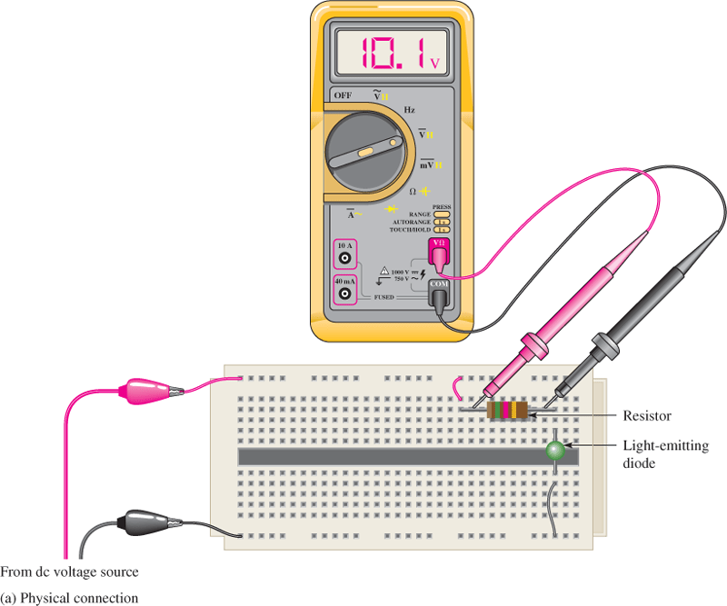
Figure 3. DC Voltage Measurement Using Digitial Multimeter
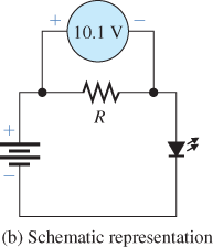
Figure 4. DC Voltage Measurement Schematic Representation
Step by Step Guide on How to Use a Digital Multimeter to Test for Current
Testing for current is used when there is no physical way to tell if a load is doing its job because there are no indicators or the load is located in a hazardous area. When the voltage is tested and found to be present at the load, it doesn’t tell the whole story until a current is measured. It is important to understand a load consumes power which is measured in watts. Watts is calculated by multiplying volts by the amps. A digital multimeter is used to measure or give a good indication of current flowing.
Current can be tested in several ways; the most reliable procedure is using a clamp meter, shown in Figure 5.
Figure 5. Clamp Meter Labeled Diagram
The advantage of using clamp meter is that measurements can be obtained even without opening the test circuit. Proper protective equipment must be worn before testing can be done.
- To test for current, determine the type of current if it is AC or DC.
- Afterward, adjust the meter dial to the suitable function to DC current or AC current.
- Adjust the range on the dial except it is an auto-ranging meter.
Testing Current with a clamp meter
- Press the thumb lever to open the clamp meter head
- Close the head once it is around a single conductor and then release the metering lever.
- Now observe the reading.
Testing Current with a Digital Multimeter
- Plug the leads into the terminals marked mA for low current or A for currents over 500mA.
- Set the dial to AC or DC current depending on the circuit being measured.
- Apply the leads to the open circuit current and observe the measurement.
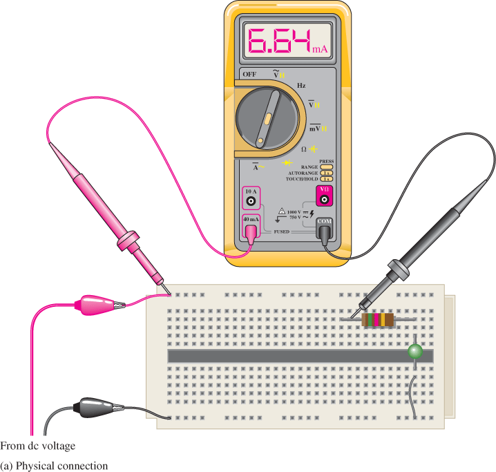
Figure 6. Current Measurement Using Digital Multimeter
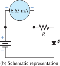
Figure 7. Current Measurement Schematic Representation
Note: For current measurements above 1A, normally clamp meter is used while for current less than 1A, a standard DMM is used.
Step by Step Guide on How to Use a Digital Multimeter to Test for Resistance
Resistance testing is done to ensure the load or circuit being tested is complete. A complete circuit means there is no break or opening in the wires connected to the load or the internal components of the device being tested. An open circuit or broken line means that the load will not work as designed. Resistance testing is sometimes referred to as continuity testing. Continuity testing does the same action as resistance testing with the exception that continuity testing emits an audible sound indicating that the circuit or wires are complete. The resistance testing and continuity testing are also a good way to check for short-circuits and the ground fault which are events that cause circuit breakers to trip, fuses to blow, and possible injury to workers in the field.
Test Resistance with a Digital Multimeter
- Turn the power off in the circuit being tested.
- Adjust the meter dial to the resistance mode.
- Choose the suitable range on the dial.
- Plug in your test leads into the suitable terminals.
- Connect the leads to the component being tested and note a reading.
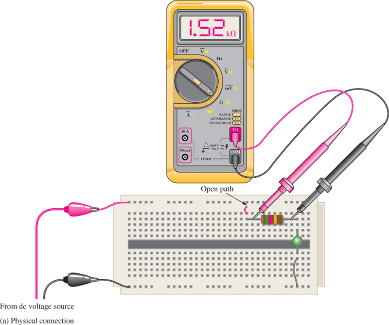
Figure 8. Resistance Measurement Using Digital Multimeter

Figure 9. Resistance Measurement Schematic Representation
Note: It is important to have good contact between the test leads and circuit being tested. Dirt, bodily contact, and poor test lead connection can considerably alter the readings.
Test Continuity with a Digital Multimeter
- Adjust the dial to the meter continuity (the little speaker) function.
- Plug the test leads into the suitable terminal.
- Touch the component under test using the leads
The DMM beeps under good continuity that allows the flow of current. If no continuity exists, the DMM does not beep.
- You May Also Read: Difference between Digital and Analog Multimeter