The article provides an overview of the main components and functions of a Programmable Logic Controller (PLC), including the power supply, input/output sections, processor, and programming section. It also covers various types of I/Os, solid-state input controls, and methods for managing electrical noise in PLC systems.
All Programmable Logic Controllers (PLCs) have four basic components. The four basic components of a Programmable Logic Controller include the power supply, input/output (I/O) section, processor section, and programming section. See Figure 1.
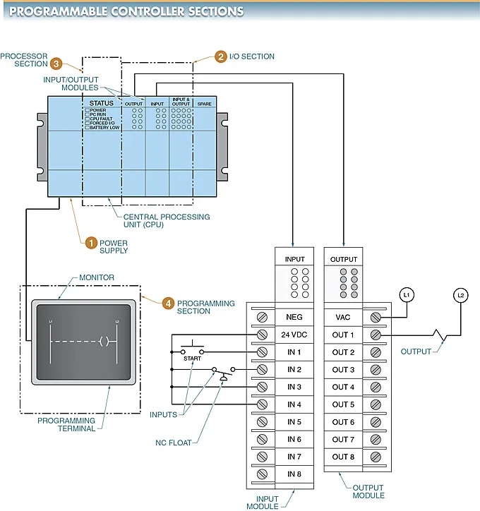
Figure 1. The four basic parts of a controller include the power supply, I/O section, processor section, and programming section.
The programs used for discrete parts manufacturing and process manufacturing are stored in and retrieved from memory as required.
Programmable Logic Controller components are interconnected and work together to allow the controller to accept inputs from a variety of sensors, make a logical decision as programmed, and control outputs such as motor starters, solenoids, valves, and drives.
Power Supplies
The power supply provides the necessary voltage levels that are required for the internal operations of the Programmable Logic Controller. In addition, it may provide power for the I/O modules. The power supply can be a separate unit or built into the processor section. It takes the incoming voltage (normally 120 VAC or 240 VAC) and changes the voltage as required (normally 5 VDC to 32 VDC).
The power supply must provide constant output voltage free of transient voltage spikes and other electrical noise. The power supply also charges an internal battery in the Programmable Logic Controller to prevent memory loss when external power is removed.
The operating life of lithium batteries, which are commonly used as power supplies for Programmable Logic Controllers, is from 3 years to 5 years.
Input/output (I/O) Sections
The input/output (I/O) sections function as the eyes, ears, and hands of a Programmable Logic Controller. The input section is designed to receive information from pushbuttons, temperature switches, pressure switches, photoelectric and proximity switches, and other sensors.
The output section is designed to deliver the output voltage required to control loads such as alarms, lights, solenoids, and starters.
The input section receives incoming signals (normally at a high voltage level) and converts them to low-power digital signals that are sent to the processor section. The processor then registers and compares the incoming signals to the program.
The output section receives low-power digital signals from the processor and converts them into high-power signals. These high-power signals can drive industrial loads that light, move, grip, rotate, extend, release, heat, and perform other functions.
The I/O sections can either be located on the Programmable Logic Controller (onboard) or be part of expansion modules.
- Onboard I/Os are a permanent part of the Programmable Logic Controller package. Expansion modules are removable units that include inputs, outputs, or combinations of inputs and outputs.
- Onboard I/Os usually include a fixed number of inputs and outputs that define the limits of the Programmable Logic Controller. For example, a small Programmable Logic Controller may include up to 16 inputs and eight outputs. This means that up to 16 inputs and eight outputs may be connected to the controller.
- Programmable Logic Controllers that use expansion modules allow the total number of inputs and/or outputs to be changed by changing or adding modules. Onboard Programmable Logic Controllers are normally used for individual machines and small systems.
- Expansion Programmable Logic Controllers are normally used for large systems or small systems that require flexible changes.
- Discrete I/Os
Discrete I/Os are the most common inputs and outputs. Discrete I/Os use bits that represent a separate and distinct signal each, such as ON/OFF, open/closed, or energized/de-energized. The processor reads this as the presence or absence of power.
Examples of discrete inputs are pushbuttons, selector switches, joysticks, relay contacts, starter contacts, temperature switches, pressure switches, level switches, flow switches, limit switches, photoelectric switches, and proximity switches. Discrete outputs include lights, relays, solenoids, starters, alarms, valves, heating elements, and motors.
- Data I/Os
In many applications, more complex information is required than the simple discrete I/O is capable of producing. For example, measuring temperature may be required as an input into the Programmable Logic Controller and numerical data may be required as an output.
Data I/Os are inputs and outputs that produce or receive a variable signal. They may be analog, which allows for monitoring and controlling analog voltages and currents, or they may be digital, such as binary-coded decimal (BCD) inputs and outputs.
- When an analog signal such as voltage or current is input into an analog input card, the signal is converted from analog to digital by an analog-to-digital (A/D) converter. The converted value, which is proportional to the analog signal, is sent to the processor section.
- After the processor has processed the information according to the program, the processor outputs the information to a digital-to-analog (D/A) converter.
- The converted signal can provide an analog voltage or current output that can be used or displayed on an instrument in a variety of processes and applications.
Examples of data inputs are potentiometers, rheostats, encoders, barcode readers, and temperature, level, pressure, humidity, and wind speed transducers. Examples of data outputs are analog meter displays, digital meter displays, stepper motor signals, variable voltage outputs, and variable current outputs.
- I/O Capacity
The size of a Programmable Logic Controller is based on the I/O capacity. Common I/O capacities of different sizes of Programmable Logic Controllers include the following:
- mini/micro (32 or fewer I/Os, but may have up to 64)
- small (64 to 128 I/Os, but may have up to 256)
- medium (256 to 512 I/Os, but may have up to 1023)
- large (1024 to 2048 I/Os, but may have many thousands more on very large units)
The I/Os may be directly connected to the Programmable Logic Controller or may be in a remote location. I/Os in a location remote from the processor section can be hardwired to the Programmable Logic Controller, multiplexed over a pair of wires, or sent by a fiber-optic cable. In any case, the remote I/O is still under the control of the central processor section. Common Programmable Logic Controllers may have 16, 32, 64, 128, or 256 remote I/Os.
Fiber-optic communication modules route signals from the inputs to the processor section and then to the outputs. Fiber-optic communication modules are unaffected by noise interference and are commonly used for process applications in the food and petrochemical industries. They are also used in hazardous locations.
- Solid-State Input Controls
Programmable Logic Controllers can have many types of inputs, including pushbuttons, level switches, temperature controls, and photoelectric controls.
Inputs such as pushbuttons and temperature controls are normally easy to input. However, more complex solid-state control inputs such as proximity and photoelectric switch inputs require special consideration because of their function.
Solid-state proximity and photoelectric controls are used in many automated systems. See Figure 2. These controls normally have a solid-state output that is ideal for input into Programmable Logic Controllers.
Photoelectric controls can be input into Programmable Logic Controllers for detection, inspection, monitoring, counting, and documentation.
Available outputs include two- and three-wire types with thyristor and transistor outputs that can be connected individually or in series/parallel combinations.
- Two-Wire Thyristor Outputs
Two-wire thyristor outputs are available in a supply voltage range of 20 VAC to 270 VAC at about 180 mA to 500 mA range in either NO or NC versions. Two-wire thyristor outputs have only two wires and are wired in series with the load, which is similar to a mechanical switch. See Figure 3.
The power to two-wire thyristor output sensors is received through the load when the load is not being operated. As with any thyristor output device, some consideration must be given to off-state leakage current and minimum load current.
Unlike a mechanical switch, the proximity sensor consumes current in the inactivated mode. The current is small enough that most industrial loads are unaffected. However, this leakage current may be enough to activate the load on some high-impedance loads and controllers.
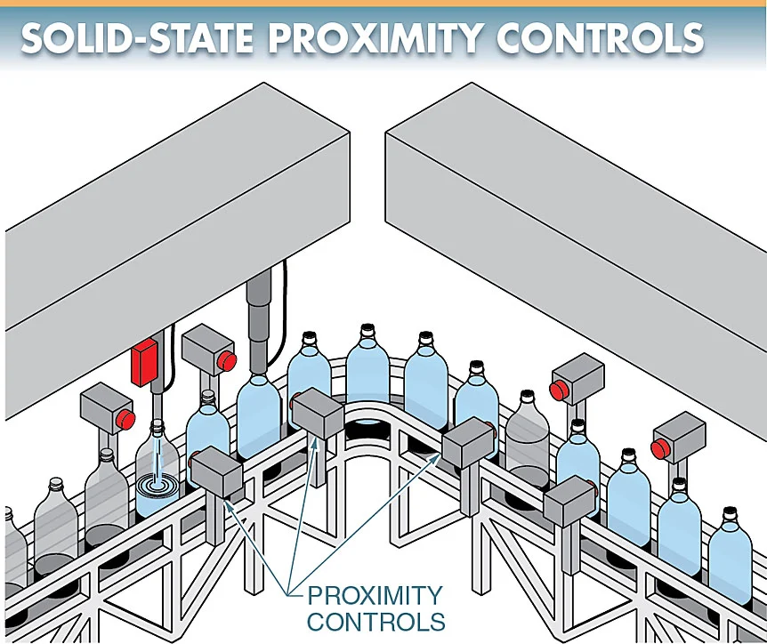
Figure 2. Solid-state proximity controls normally have a solid- state output that is ideal for input into Programmable Logic Controllers.
The leakage current problem can be corrected by placing a load resistor across the input device. See Figure 4. The resistor value should be chosen to ensure that a minimum load current is exceeded and the effective load impedance is reduced. This prevents off-state leakage current turn-on. This resistance value is normally in the range of 4.5 kΩ to 7.5 kΩ. A general rule is to use a 5 kΩ, 5 W resistor for most applications.
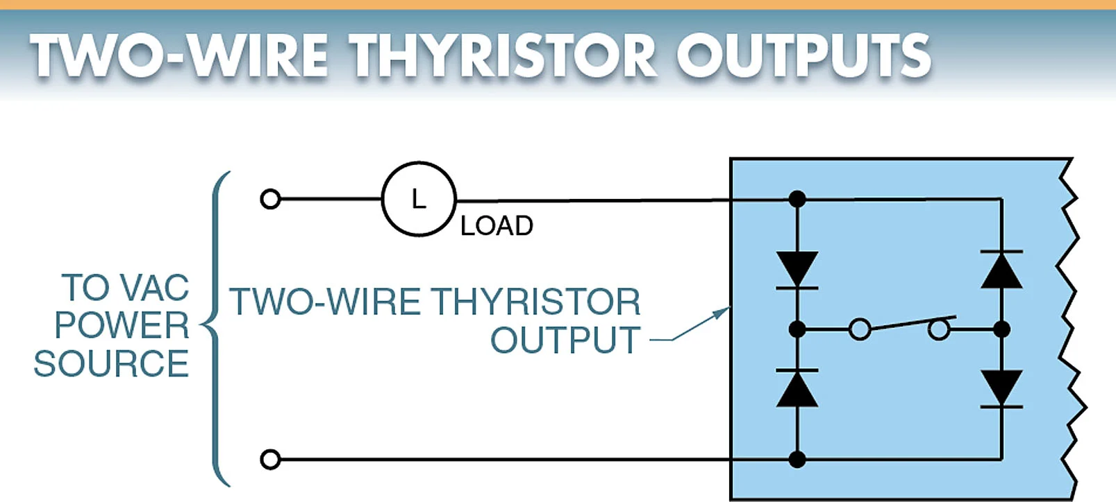
Figure 3. Two-wire thyristor outputs have only two wires and are wired in series with the load, which is similar to a mechanical switch.
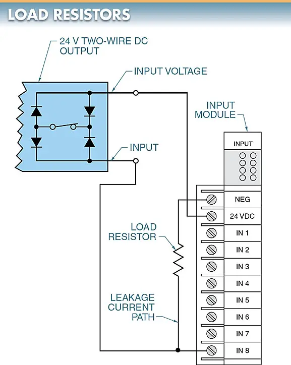
Figure 4. A load resistor may be required when connecting a sensor to the controller to prevent leakage current from being input into the controller.
- Electrical Noise Suppression
Electrical noise is unwanted signals that are present on a power line. Electrical noise enters through input devices, output devices, and power supply lines.
Unwanted noise pickup may be reduced by placing the Programmable Logic Controller away from noise-generating equipment such as motors, motor starters, welders, and drives. Noise suppression should be included in every Programmable Logic Controller installation because it is impossible to eliminate noise in an industrial environment.
Certain sensitive input devices (analog and digital) require a shielded cable to reduce electrical noise. A shielded cable uses an outer conductive jacket (shield) to surround the two-inner signal-carrying conductors. The shield blocks electromagnetic interference. The shield must be properly grounded to be effective. Proper grounding includes grounding the shield at only one point. A shield grounded at two points tends to conduct current between the two grounds.
Low-voltage DC signals must not be routed near high-voltage (120 V) AC signals. If the signals must cross, it is important to ensure that the cables cross at 90° to minimize interference. See Figure 5.
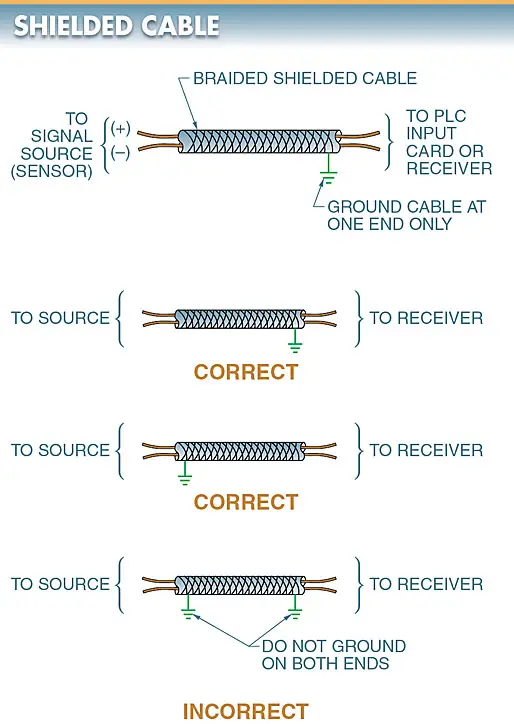
Figure 5. A shielded cable uses an outer conductive jacket (shield) that blocks magnetic interference from the two-inner signal-carrying conductors.
A high-voltage spike is produced when inductive loads such as motors, solenoids, and coils are turned off. These spikes may cause problems in a Programmable Logic Controller. High-voltage spikes should be suppressed to prevent problems. A snubber circuit is used to suppress a voltage spike. Typical snubber circuits use an RC (resistor/capacitor), MOV (metal-oxide varistor), or diode, depending on the load. See Figure 6.
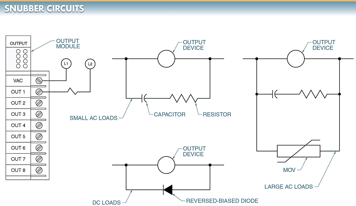
Figure 6. Snubber circuits are used to suppress voltage spikes in controllers.
- Three-Wire Transistor Outputs
Three-wire transistor outputs are available in a supply range of 10 VDC to 40 VDC at about 200 mA. These sensors are easily interfaced with other electronic circuitry and Programmable Logic Controllers.
Output sensor types consist of either an open collector NPN or PNP transistor. Both normally open (NO) or normally closed (NC) versions are available.
These output devices receive their power to operate through two of the leads (positive and negative, respectively) from the power source. The third lead is used to switch power to the load either using the same source of power as the proximity switch or an independent source of power. See Figure 7.
- You May Also Read: Programmable Logic Controller (PLC) Questions Answers
When an independent source is used, one lead of that source is common with one lead of the source used to power the output device. The voltage level must be within the specifications of the output device used when using an independent power source for the load.
Processor Sections
The processor section is the section of a Programmable Logic Controller that organizes all control activity by receiving inputs, performing logical decisions according to the program, and controlling the outputs.
The processor section is the brain of the Programmable Logic Controller and can be referred to as the central processing unit (CPU). See Figure 8.
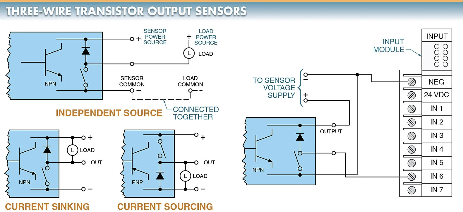
Figure 7. Three-wire transistor output sensors use either NPN or PNP transistors to control the load.
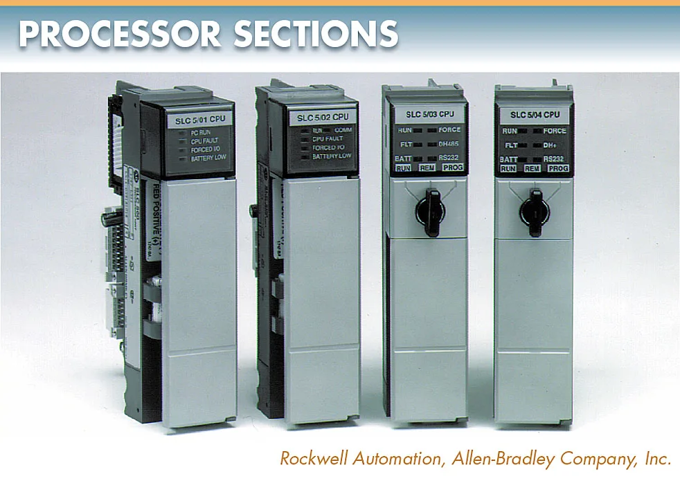 Figure 8. The processor section organizes all control activity by receiving inputs, performing logical decisions, and controlling the outputs.
The processor section evaluates all input signals and levels. This data is compared to the memory in the Programmable Logic Controller, which contains the logic of how the inputs are interconnected in the circuit. The interconnections are programmed into the processor by the programming section. The processor section controls the outputs based on the input conditions and the program.
The processor continuously examines the status of the inputs and outputs and updates them according to the program. See Figure 9. Scan is the process of evaluating the I/O status, executing the program, and updating the system.
Scan time is the time it takes a Programmable Logic Controller to make a sweep of the program.
Scan time is normally given as the time per 1 kilobyte (kB) of memory and is normally listed in milliseconds (ms). Scanning is a continuous and sequential process of checking the status of inputs, evaluating the logic, and updating the outputs.
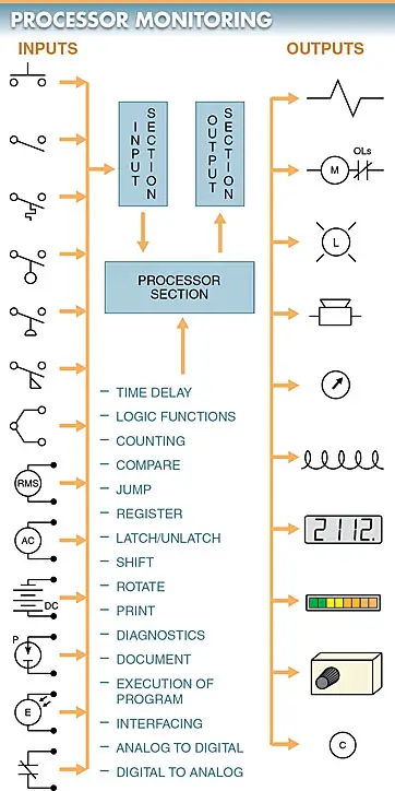
Figure 9. The processor continuously examines the status of the inputs and outputs and updates them according to the program.
The processor section of a Programmable Logic Controller has different modes. The different modes allow the controller to be taken on-line (system running) or off-line (system on standby). Processor modes include the program, run, and test modes. See Figure 10.
The program mode is used for developing the logic of the control circuit. In the program mode, the circuit is monitored and the program is edited, changed, saved, and transferred.
The run mode is used to execute the program. In the run mode, the circuit may be monitored and the inputs and outputs forced. Program changes cannot normally be made in the run mode. The test mode is used to check the program without energizing output circuits or devices.
In the test mode, the circuit is monitored and inputs and outputs are forced in the program (without actually energizing the load connected to the output).
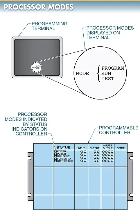
Figure 10. The processor section of a controller has different modes that allow the controller to be taken on-line (system running) or off-line (system on standby).
Programming Sections
The programming section is the section of a Programmable Logic Controller that allows input into the controller through a keyboard.
The processor must be given exact, step-by-step directions. This means things such as load, set, reset, clear, enter in, move, and start timing must be communicated to the processor. The programming of a controller involves the programming device that allows access to the processor and the programming language that allows the operator to communicate with the processor section.
Programming Devices
Programming devices vary in size, capability, and function. Programming devices are available as simple, small text display units or complex color displays with monitoring and graphics capabilities. See Figure 11.
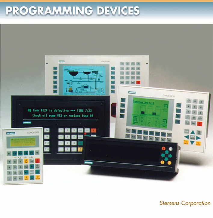
Figure 11. Programming devices are available as simple, small text display units or complex color displays with monitoring and graphics capabilities.
Programmable Logic Controller (PLC) Key Takeaways
Understanding the key components and functions of a Programmable Logic Controller (PLC)—including the power supply, input/output sections, processor, and programming interface—is essential for ensuring reliable and efficient industrial automation. These elements work together to control complex systems with precision and flexibility. The variety of input/output types, such as discrete and data I/Os, allows PLCs to adapt to a wide range of applications, from simple motor control to sophisticated process automation. Furthermore, solid-state input controls and proper electrical noise suppression enhance the accuracy, longevity, and safety of these systems.