Types of Resistors
As you know, a resistor is a component that is designed to provide specific amount of resistance. Resistors are classified as being either fixed or variable. A FIXED RESISTOR is one that has specific ohmic value that cannot be changed by the user. A VARIABLE RESISTOR is one that can be adjusted to any ohmic value within a specified range. Several fixed and variable resistors are shown in Figure 1. Note that variable resistors all have some mechanism for manually adjusting the component’s resistance value.
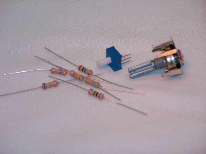
Figure 1 Types of Fixed and variable resistors.
Carbon Composition Resistor
The most commonly used resistor is the CARBON COMPOSITION RESISTOR. The conductance of the carbon composition resistor is illustrated in Figure 2. As you can see, the resistor has two metal leads (conductors) that are separated by carbon. When current enters the resistor, it passes through the carbon that separates the leads, as shown in Figure 3. The relatively high resistivity of the carbon is the source of the resistor’s opposition to current.
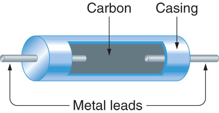
Figure 2 Carbon composition resistor.
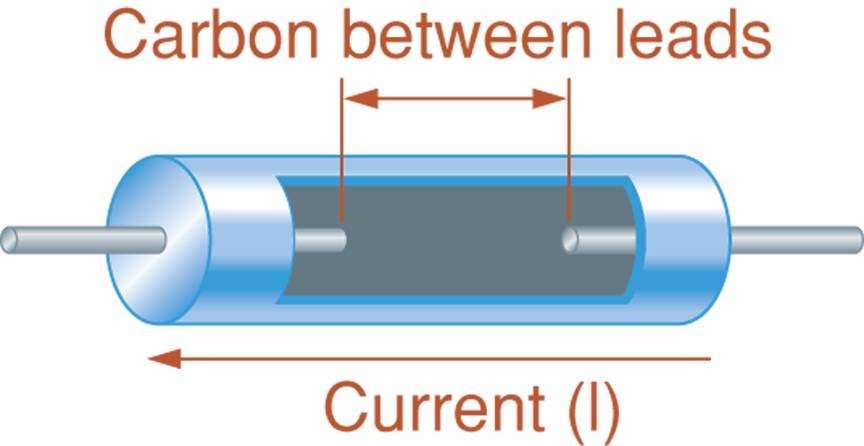
Figure 3 Current passing through a resistor.
The value of the carbon-composition resistor is determined primarily by the purity of the carbon. By adding IMPURITIES (other elements) to carbon during the manufacturing process, the resistivity of the carbon can be increased or decreased, depending on the amount and type of impurity used. Controlling the impurity levels makes it possible to produce carbon composition resistors with a wide range of values.

Figure 4 Resistor manufacturing environment.
Other Types of Resistors
A WIRE WOUND RESISTOR uses the resistivity of a length of wire as the source of its resistance. A wire-wound resistor is illustrated in Figure 5. The value of the component is determined by the length of the wire between the leads. The longer the wire, the higher the resistance of the component.
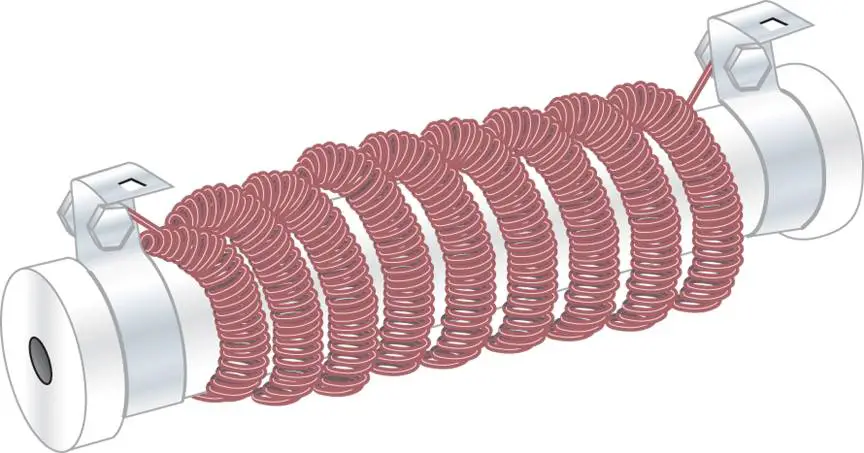
Figure 5 Wire-wound resistor construction.
Wire wound resistors are used primarily in high-power applications; that is, applications where components must be able to dissipate (throw off) a relatively high amount of heat. A wire-wound resistor has more surface area than a comparable carbon-composition resistor, so it can dissipate more heat.
Integrated Resistors
Integrated resistors are micro-miniature components that are made using semiconductors other than carbon. Integrated resistors have the advantage of being extremely small. These resistors are so small that several of them can be packaged in a single casing like the one shown in Figure 6a. The case shown contains seven resistors that are connected between the pins as shown in Figure 6b. Integrated are restricted to low-current applications.
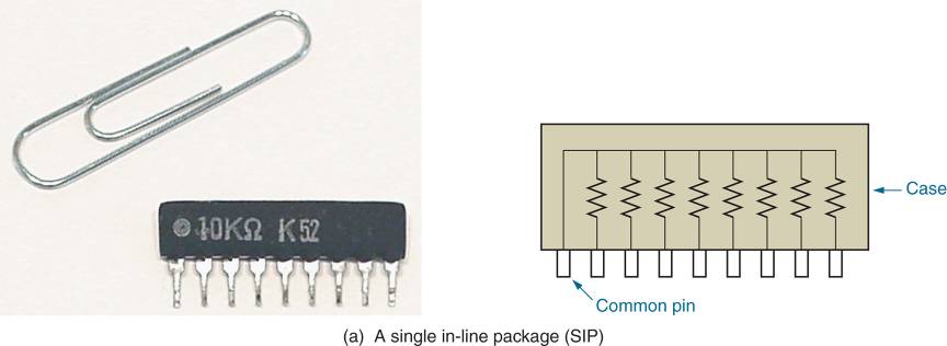
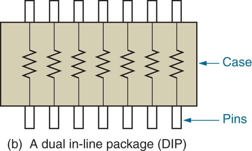
FIGURE 6a-6b integrated resistors.
Standard Resistor Values
Resistors are commercially produced in variety of values. The standard resistor values are listen in Table 1.
Table 1: Standard Resistors Values
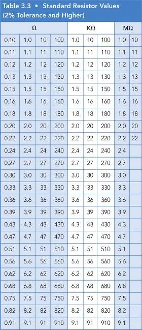
If you look at any row of numbers in the table, you’ll see that it contains a series of values that all start with the same two digits. The only difference between the values is the power of ten multiplier, for example, the values shown in the first row from left to right could be written as follows;
$\begin{align}& 10\times {{10}^{-2}} \\& 10\times {{10}^{-1}} \\& 10\times {{10}^{0}} \\& 10\times {{10}^{1}} \\& 10\times {{10}^{2}} \\& 10\times {{10}^{3}} \\& 10\times {{10}^{4}} \\& 10\times {{10}^{5}} \\\end{align}$
As these values indicate, we can designate any resistor value using only the first two digits and power of ten multiplier. As you will see, this is the basis for the resistor color code.
Resistor Tolerance
Even with advanced production techniques, there is almost always some difference between the actual and rated values of a resistor. For example a resistor rated at 100Ω might have an actual value of 98Ω or 104Ω. Slight variations like these in component values are common occurrences.
Even through resistor values aren’t always exact, they can be guaranteed to fall within a specified range of values. For example, a manufacturer may be able to guarantee that the actual value of every 100Ω resistor will fall between 95Ω and 105Ω. This range of values is called the TOLERANCE of the component, and is given as a percentage of its rated value.
Most common resistors have 2% or 5% tolerance ratings. This means that their actual values are guaranteed to fall within ±2% or ±5% of their rated values. Some older resistors have 10% and 20% tolerance ratings, but these components are not found in modern electrical and electronic systems.
Integrated resistors like these shown in Figure 6 often have very poor tolerance ratings –as high as 30% in some cases. As a result, their use is limited to circuits that can handle wide variations in resistance.
To determine the range of possible values for a resistor:
1. Multiply the rated value of the resistor by its tolerance to find its minimum variation in resistance.
2. Add the minimum variation to the rated value of the component to find its upper limit.
3. Subtract the maximum variation from the rated value of the component to find the lower limit.
This procedure is illustrated in the following example.
Resistor Value Calculation Example 1
Determine the range of possible values for a 470Ω resistor that has a 5 % tolerance.
Solution
First, the maximum variation is resistance is found as
$470\Omega \times 0.05=23.5\Omega $
The maximum variation is now added to the rated value of the component, as follows:
$\begin{matrix}470\Omega +23.5\Omega =493.5\Omega & {} & \text{upper limit} \\\end{matrix}$
The maximum variation is now subtracted from the rated value of the component, as follows:
$\begin{matrix}470\Omega -23.5\Omega =446.5\Omega & {} & \text{lower limit} \\\end{matrix}$
The range of possible values for this resistor is 446.5 Ω to 493.5 Ω.
The higher the tolerance of the resistor, the wider its range of possible values. This point is illustrated in the Following example.
Resistor Value Calculation Example 2
Determine the range of possible values for a 33kΩ resistor with a 2 % tolerance and a 33kΩ resistor with a 5 % tolerance.
Solution
For the 2% tolerance resistor:
\[\begin{align}& 33k\Omega \times 0.02=660\Omega \\& \begin{matrix}33k\Omega +660\Omega =33.66k\Omega & {} & \text{upper limit} \\\end{matrix} \\& \begin{matrix}33k\Omega -660\Omega =32.34k\Omega & {} & \text{lower limit} \\\end{matrix} \\\end{align}\]
For the 5% tolerance resistor:
\[\begin{align}& 33k\Omega \times 0.05=1650\Omega \\& \begin{matrix}33k\Omega +1650\Omega =34.65k\Omega & {} & \text{upper limit} \\\end{matrix} \\& \begin{matrix}33k\Omega -1650\Omega =31.35k\Omega & {} & \text{lower limit} \\\end{matrix} \\\end{align}\]
These results show that 5% tolerance component has a wide range of possible values.
Lower tolerance components are considered to be higher –quality components. In fact, the ideal (perfect) resistor, if it could be produced, would have tolerance rating of 0%. This means its rated and measured values would always be equal.
Even though they are no longer produced, you may see the resistors with tolerances of 10% in older circuits and systems. Later in this section, you’ll be shown how a tolerance of a resistor is indicated.
Resistor Color Code
In most cases, the value of the resistor is indicated by a series of color bands on the component. For example, look at the resistor shown in Figure 7. The resistor has four color bands. These bands are numbered as shown in the figure. Note that the fourth band is offset of the first three.
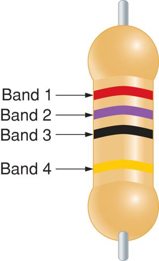
Figure 7 Resistor color bands example
The first three bands on a resistor is designated its rated value as follows:
Band 1: The color of this band designates the first digit in the resistor value.
Band 2: The color of this band designates the second digit in the resistor value.
Band 3: The color of this band designates the power-of-ten multiplier for the first two digits. (In most cases, this is simply the number of zeros that follow the first two digits)
The colors that most often appear in these three bands are coded as shown in Figure 8.
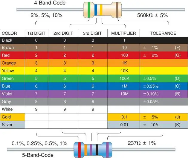
Figure 8 The standard resistor color code Chart
The following series of examples shows how the first three color bands are used to indicate the values of a given resistor.
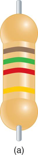
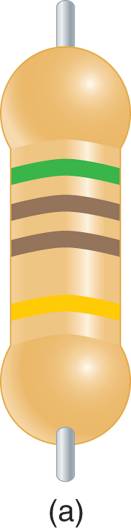
3-Band Resistor Color Code Example 3
Determine the rated value of the resistor shown in figure 9.
Solution
Brown=1, so the first digit in the resistor value is 1.
Green=5, so the second digit in the resistor value is 5.
Red=2, so the power of ten multiplier is 102=100.
Combining these values we get,
$\left( 15\times 100 \right)\Omega =1500\Omega =1.5k\Omega $
Note that the multiplier band value (2) is equal to the number of zeros in the value of the resistor.
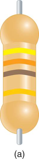
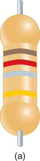
3-Band Resistor Color Code Example 4
Determine the rated value of the resistor shown in figure 10.
Solution
Yellow=4, so the first digit in the resistor value is 4.
Orange=3, so the second digit in the resistor value is 3.
Brown=1, so the power of ten multiplier is 101=10.
Combining these values we get,
$\left( 43\times 10 \right)\Omega =430\Omega =0.43k\Omega $
Note that the multiplier band told us the number of zeros following the first two digits of the component’s value.
When the multiplier band on a resistor is black, you have to be careful not to make a common mistake. Entry level technicians will often see a black multiplier band, see that black corresponds to zero, and assume that there is a zero after the first two digits. A black multiplier band indicates that there are no zeros following the first two digits. This point is illustrated in the following example.
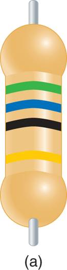
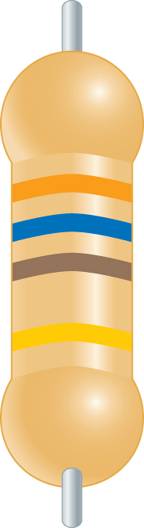
3-Band Resistor Color Code Example 5
Determine the rated value of the resistor shown in figure 11.
Solution
Green=5, so the first digit in the resistor value is 5.
Blue=6, so the second digit in the resistor value is 6.
Black=0, so the power of ten multiplier is 100=1.
Combining these values we get,
$\left( 56\times 1 \right)\Omega =56\Omega $
Note that no resistors are added after the first two digits. This is always the case when the multiplier band is black.
There are two other colors that may appear in the multiplier ban. These colors and their multiplier values are as follows:
GOLD = -1
SILVER = -2
When the multiplier band is gold, decimal point is added between the first two digits in the value. This is illustrated in the following example.
3-Band Resistor Color Code Example 6
Determine the rated value of the resistor shown in figure 12.
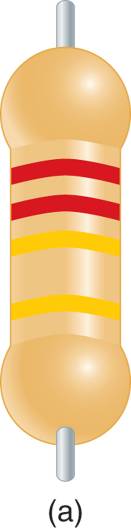
Solution
Red=2, so the first digit in the resistor value is 2.
Red=2, so the second digit in the resistor value is 2.
Gold=-1, so the power of ten multiplier is 10-1=0.1.
Combining these values we get,
$\left( 22\times 0.1 \right)\Omega =2.2\Omega $
As you can see, a gold multiplier band indicates that a decimal point is placed between the first two digits in the resistor’s value.
When the multiplier band is silver, a decimal point is added in front of the two digits in the component value. This is illustrated in the following example.
3-Band Resistor Color Code Example 7
Determine the rated value of the resistor shown in figure 13.
Solution
Brown=1, so the first digit in the resistor value is 1.
Red=2, so the second digit in the resistor value is 2.
Silver=-2, so the power of ten multiplier is 10-2=0.01.
Combining these values we get,
$\left( 12\times 0.01 \right)\Omega =0.12\Omega $
As you can see, a silver multiplier band indicates that a decimal point is placed in front of the first two digits in the resistor’s value.
As often as not, you’ll need to able to determine the color code for a specific value of resistance so that you can locate the needed component. When this is the case, write the component value in standard form. The first two colors are determined by the first two digits. The color of the multiplier band is determined (in more cases) by the number of zeros that follow the first two digits. This is illustrated in the following example.
Determine Resistor Color Code Example 8
You need to locate a 360 Ω resistor. Determine the colors of the first three bands on the components?
Solution
The first three bands are coded for 3, 6, and 1 (which is the number of zeros in the value). The colors that correspond to these numbers are as follows:
$\begin{matrix}3 & = & Orange \\6 & = & Blue \\1 & = & Brown \\\end{matrix}$
Resistor Tolerance
The fourth band on a resistor designates its tolerance. The colors used in tolerance band of four-band resistors are as follows:
Red = 2%
Gold = 5%
Silver = 10%.
The following example shows how the first four bands on a resistor are used to determine the range of possible values for the component.
Resistor Value Calculation Example 9
Determine the range of possible values for the resistor in Figure 14.
Solution
Green =5, so the first digit in the component value is 5.
Brown=1, so the second digit in the component value is 1.
Brown=1, so the multiplier is 101=1
Gold=5% (the tolerance of the component)
The first three bands indicate that the rated value of the component is 510Ω, and
\[\begin{align}& 510\Omega \times 0.05=25.5\Omega \\& \begin{matrix}510\Omega +25.5\Omega =535.5\Omega & {} & \text{upper limit} \\\end{matrix} \\& \begin{matrix}510\Omega -25.5\Omega =485.5\Omega & {} & \text{lower limit} \\\end{matrix} \\\end{align}\]
Review Questions
Describe the physical composition of carbon composition resistor?
A carbon-composition resistor is comprised of two leads separated by a carbon body. The resistance is determined by the purity of the carbon.
How is the value of carbon-composition resistor indicated?
In most cases, color bands are used to indicate the resistor value.
In what applications are wire-wound resistors primarily used?
Wire-wound resistors are usually used in high-power applications. Their greater surface area allows them to dissipate more heat.
What are integrated resistors?
Integrated resistors are semi-conductor based miniature resistors. Usually several are packaged in a single case.
What is the tolerance of the resistor?
Tolerance is the range of values that the actual value of a resistor is guaranteed to fall within, usually expressed as a percentage.
How do you determine the range of possible values for a resistor?
First multiply the nominal value of the resistor by its tolerance to find the maximum variation. Then subtract this value from the nominal (rated) value to find the lowest possible value and add it to the rated value to find the highest possible value. For example, a 100 Ω resistor with a 5% tolerance rating will fall within the range of 95 Ω to 105 Ω.
What is indicated by the color of each of the first three bands on the resistor?
The first band indicates the first digit of the resistor value. The second band indicates the second digit of the resistor value. The third band indicates the power-of-ten multiplier.
What is indicated by a black multiplier band on a resistor?
A black (0) multiplier band means that there are no zeroes following the first two digits.
What is indicated by a gold multiplier band on a resistor?
A gold multiplier band means multiplication by 0.1, or 10-1.
How do you determine the color code for a specific standard resistor value?
The first two colors on the color band represent the first two digits of the resistance value. The third band represents the number of zeroes that follow these two digits. For example, A 4.7 kΩ resistor would have color bands of yellow-violet-red (4-7-2).
What does the fourth color band on a resistor indicate?
The fourth color band is the tolerance band.
List the colors that are commonly found in the fourth band and give the value that is indicated by each of them.
The three standard tolerance colors are, red = 2%, gold = 5%, and silver = 10.
Resistor Color Code and Resistor Tolerance Key Takeaways
Resistors play a crucial role in electrical and electronic applications, ensuring precise current control, voltage regulation, and circuit protection. Fixed and variable resistors, along with specialized types like carbon composition, wire-wound, and integrated resistors, cater to a wide range of requirements, from power dissipation in industrial equipment to miniaturization in modern electronics. Understanding standard resistor values, tolerance levels, and color codes is essential for accurate circuit design and troubleshooting. These components form the backbone of countless devices, from household electronics to advanced computing systems.