This article covers Norton’s Theorem and Norton’s Equivalent Circuit Parameters, such as Norton’s Equivalent Resistance and Short-circuit Current, along with Norton’s Theorem Solved Problem with Dependent Sources.
What is Norton’s Theorem?
Norton’s Theorem states that any two-terminal electric network comprising resistances and voltage and/or current sources may be substituted with a single current source connected in a parallel configuration with a single resistance. The current source output is the short-circuit current at the terminals of a network, whereas the parallel resistance is the resistance between the terminals of a network when all the sources are set to zero.
Find the Norton’s Equivalent Circuit
Suppose we are given an arbitrary circuit containing any or all of the following elements: resistors, voltage sources, and current sources (the source can be dependent as well as independent). Let us identify a pair of nodes, say nodes a and b, such that the circuit can be partitioned into two parts, as shown in Figure 1.
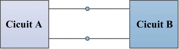
Figure.1: Circuit partitioned into two parts
Furthermore, suppose that circuit A contains no dependent source that is dependent on a variable in circuit B, and vice versa. Then, we can model circuit A by an appropriate independent current source, call it isc, which is connected in parallel with an appropriate resistance, call it RN. This parallel combination of a current source and resistance is called Norton’s equivalent of circuit A. In other words, circuit A in Figure 1, and the circuit in the shaded box in Figure 2 have the same effect on circuit B. This result is known as Norton’s theorem.
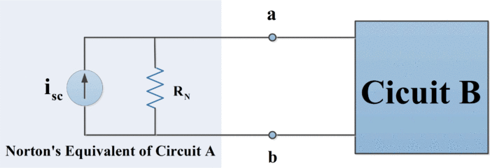
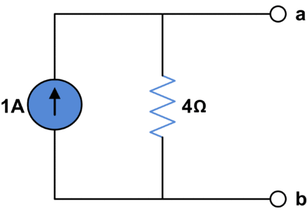
Figure.2: Norton’s Equivalent Circuit
Circuit B (which is often called a load) may consist of many circuit elements, a single element ( a load resistor), or no element.
- You May Also Read: Thevenin’s Theorem with Solved Examples
Norton’s Short Circuit Current
To obtain Norton’s equivalent of some circuit A, determine the short-circuit current isc by placing a short circuit between nodes a and b and then calculate the resulting current (directed from the terminal a to b through the short circuit).
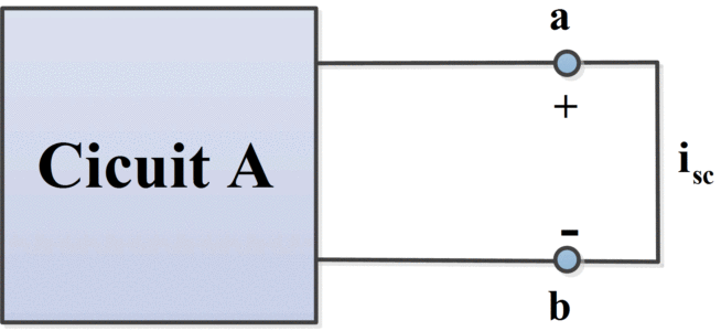
Figure.3 (a): Determination of short-circuit current
How to Find Norton’s Equivalent Resistance
There are several ways to find Norton’s equivalent resistance, which are given below:
1. To obtain the resistance RN– called Norton’s equivalent resistance of circuit A:
I. Remove circuit B from circuit A.
II. Set all independent sources in circuit A to zero. (A zero voltage source is equivalent to a short circuit, and a zero current source is equivalent to an open circuit).
III. Determine the resistance between nodes a and b- this is RN– as shown in figure 3(b).
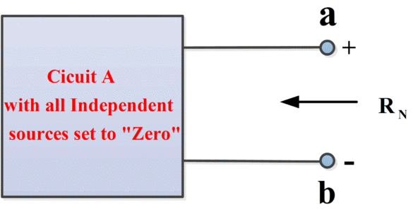
Figure.3 (b): Determination of Norton’s Equivalent Resistance
2. Short-circuit the terminals a and b, then find the short-circuit current Isc. Norton’s equivalent resistance is given by
\[{{\text{R}}_{\text{N}}}\text{ = }{{\text{V}}_{\text{oc}}}\text{/}{{\text{I}}_{\text{sc}}}\text{ = }{{\text{V}}_{\text{th}}}\text{/}{{\text{I}}_{\text{sc}}}\]
Whereas Voc or Vth can be found as was done for the Thevenin equivalent circuit.
3. When the source network has a ladder structure and contains no controlled (dependent) sources, RN is easily found by series-parallel reduction of the dead network. When the source network contains controlled sources, Norton’s equivalent resistance can be found using the method represented in figure 4.
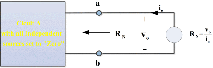
Figure.4: Find Norton’s Equivalent Resistance
Here, the dead source network has been connected to an external test source. This test source may be any independent voltage or current source that establishes vo and it at the terminals. Since the dead network contains only resistors and controlled sources, and since RN equals the equivalent resistance of the dead network, the equivalent resistance theorem tells us that
\[{{\text{R}}_{\text{N}}}\text{=}{{\text{v}}_{\text{o}}}\text{/}{{\text{i}}_{\text{o}}}\]
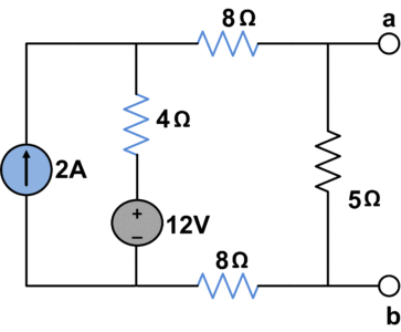
Norton’s Theorem Solved Example
Find Norton’s Equivalent circuit of the following circuit.
Let’s find Norton Equivalent resistance RN
- Open circuit all current sources
- Short circuit all voltage sources
Now, we have the following circuit to calculate RN
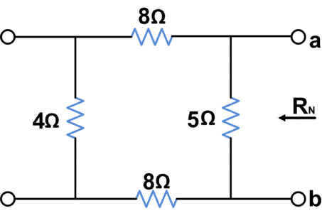
\[{{R}_{N}}=\text{ }5||\text{ }\left( 8+4+8 \right)\]
\[{{R}_{N}}=4\text{ }\Omega \]
In order to find short-circuit current isc, we short-circuit terminals a and b:
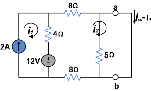
Using loop analysis we have;
\[{{i}_{1}}=2A\]
$20{{i}_{2}}-4{{i}_{1}}-12=0$
\[{{i}_{2}}=1A\]
So;
\[{{I}_{N}}={{i}_{sc}}={{i}_{2}}=1A\]
Hence we have followed Norton’s equivalent circuit
Norton’s Theorem Solved Problem with Dependent Sources
We will find Isc and RN for the circuit shown in the following figure.
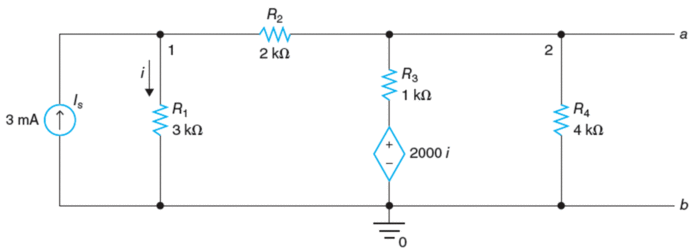
In order to determine the short-circuit current, we’ll short-circuit terminals a and b as shown in the following figure and V2 = 0.
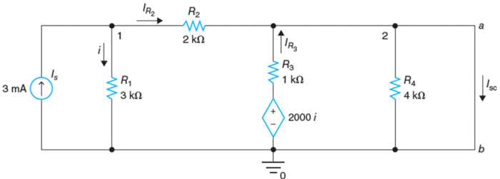
Apply KCL to node 1:
\[\begin{matrix} -0.003+\frac{{{V}_{1}}}{3000}+\frac{{{V}_{1}}}{2000}=0 & \cdots & (1) \\\end{matrix}\]
Multiplying (1) by 6000 yields:
\[\begin{align} & 5{{V}_{1}}=\text{ }18 \\ & {{V}_{1}}=\text{ }3.6\text{ }V \\\end{align}\]
Now, calculating currents:
\[i=\text{ }{{V}_{1}}/3000\text{ }=\text{ }3.6\text{ }V/3000\Omega =\text{ }0.0012\text{ }A\]
\[{{V}_{CCVS}}=\text{ }2000i\text{ }=\text{ }2.4\text{ }V\]
\[{{I}_{{{R}_{2}}}}=\text{ }{{V}_{1}}/{{R}_{2}}=1.8mA\]
\[{{I}_{{{R}_{3}}}}=\text{ }{{V}_{CCVS}}/{{R}_{3}}=2.4mA\]
Finally, IN would be
\[{{I}_{N}}={{I}_{{{R}_{2}}}}+\text{ }{{I}_{{{R}_{3}}}}~=\text{ }1.8mA+\text{ }2.4mA=\text{ }4.2mA\]
In order to determine RN, and deactivate the current source, a test voltage of 1 V is applied across terminals a and b as shown in the following figure. Vt = 1 V.
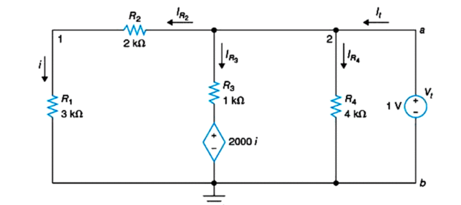
\[{{I}_{{{R}_{2}}}}=i={{V}_{t}}/({{R}_{1}}+\text{ }{{R}_{2}})\text{ }=\text{ }1\text{ }V/5\text{ }k\Omega =0.2mA\]
\[{{V}_{CCVS}}=\text{ }2000i\text{ }=\text{ }0.4\text{ }V\]
\[{{I}_{{{R}_{3}}}}=\text{ }({{V}_{t}}\text{- }{{V}_{CCVS}})/{{R}_{3}}=0.6mA\]
\[{{I}_{{{R}_{4}}}}={{V}_{t}}/{{R}_{4}}=0.25mA\]
\[{{I}_{t}}={{I}_{{{R}_{2}}}}~+{{I}_{{{R}_{3}}}}~+{{I}_{{{R}_{4}}}}=\text{ }0.2mA+\text{ }0.6mA+\text{ }0.25mA=\text{ }1.05mA\]
Noe, Norton’s equivalent resistance can be found as
\[{{R}_{N}}={{V}_{t}}/{{I}_{t}}=\text{ }952.381\Omega \]
Summary of Norton’s Theorem Steps
The following steps can be carried out for solving a circuit using Norton’s Theorem:
- The Portion of the circuit considered as the load is removed
- The short circuit current isc is calculated at terminals
- To calculate RN:
- Short circuit all independent voltage sources
- Open circuit all independent current sources
- Draw Norton’s equivalent circuit, connect the load, and calculate the load current.
Norton’s Theorem and Norton’s Equivalent Circuit Key Takeaways
Understanding Norton’s Theorem and its equivalent circuit parameters—specifically, the Norton equivalent resistance (RN) and the short-circuit current (IN)—is crucial for simplifying complex electrical networks into manageable forms. These simplifications are not just theoretical; they have significant real-world applications in circuit analysis, design, and troubleshooting. Whether dealing with power systems, signal processing, or electronic circuit design, applying Norton’s Theorem enables engineers to isolate parts of a circuit for easier computation and optimization. Moreover, being able to analyze circuits with dependent sources further enhances its practical relevance, particularly in advanced systems involving amplifiers and feedback networks. In essence, Norton’s Theorem provides a powerful toolset for efficient and accurate circuit analysis across a wide range of electrical and electronic applications.