The article explains the principles and operation of two types of analog meter movements: the D’Arsonval movement, which uses a rotating coil in a magnetic field to measure current, and the iron vane meter movement, which uses repelling iron pieces in a solenoid to measure voltage or current. It also covers meter scales, range selectors, and how to interpret readings from these instruments.
A common type of meter movement measures current and voltage. It is the D’Arsonval movement, or stationary magnet, moving-coil galvanometer, Figure 1. The movement consists of a permanent-type magnet and a rotating coil in the magnetic field. An indicating needle is attached to the rotating coil, Figure 2.
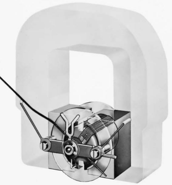
Figure 1. A phantom view of the D’Arsonval meter movement.
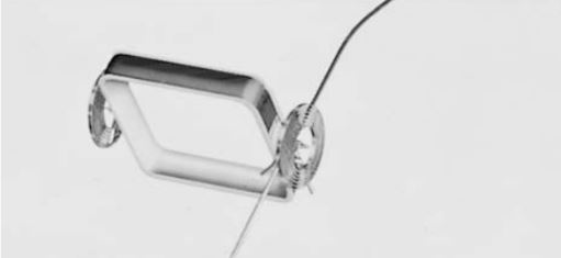
Figure 2. On the D’Arsonval, the indicating needle is attached to a rotating coil on the meter.
D’Arsonval Meter Movement Principle
When a current passes through the moving coil, a magnetic field is produced. This field reacts with the stationary field and causes rotation (deflection) of the needle. This deflection force is proportional to the strength of the current flowing in the moving coil.
When the current ceases to flow, the moving coil is returned to its “at rest” position by hairsprings. These springs are also connected to the meter coil. The deflecting force rotates the coil against the restraining force of these springs. See Figure 3.
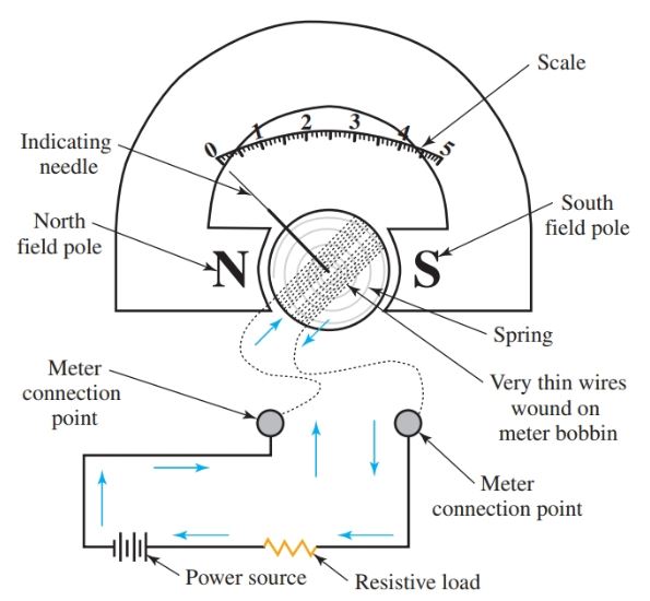
Figure 3. Current flowing through the ammeter must be limited by a resistance in the circuit being tested.
Caution
The coil that rotates in the magnetic field is mounted on precision-type jewel bearings much like a fine watch. The jewel-type bearings and mount, known as a D’Arsonval movement, make the instrument very easy to damage if dropped or jarred. Extreme caution should be used when transporting or moving a meter with a D’ Arsonval type of movement.
When connecting a meter to an electrical circuit, proper polarity must be maintained. The meter is equipped with polarity markings, usually a red plus sign (+) and a black negative sign (–). Some meters use the abbreviation COM, which stands for common, for the negative polarity marking.
The meter coil rotates inside the permanent magnet field. If the proper polarity is not used, the coil will deflect in the direction opposite to that which it was designed. At the very least, the needle will not deflect, and there will appear to be no reading. At worst, this situation could possibly damage the meter.
Some meters have circuit protection built into them. This protects the meter movement from damage that can be caused by the improper connection.
Iron Vane Meter Movement Principle
The operation principle of the iron vane meter movement is shown in Figure 4.
Two pieces of the iron are placed in the hollow core of a solenoid (a coil of wire). When the current passes through the solenoid, both pieces of metal become magnetized with the same polarity. Because like poles repel each other, the two pieces of iron are repelled from each other.
One piece of metal is fixed in its position. The other piece of metal pivots. The pivoting piece can turn away from the fixed metal.
An indicating needle is attached to the moving vane. The needle is equipped with hairsprings so that the vane must move against the spring tension for accurate readings.
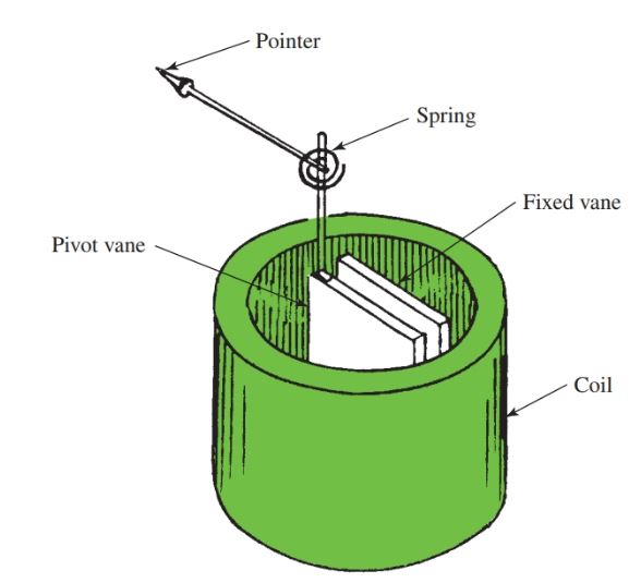
Figure 4. Operating principle of the iron vane meter movement.
An applied voltage causes current to flow in the solenoid and creates the magnetic field. The moving vane is repelled against the spring according to the strength of the magnetic field. The needle may indicate either voltage or current. It is calibrated for the magnitude (average size) of the applied voltage or current.
When the iron vane movement is used for a voltmeter, the solenoid is commonly wound with many turns of fine wire. Proper multiplier resistance may be used to increase the range of the meter. A selector switch is used to select proper ranges.
When used as an ammeter, the solenoid has a few turns of heavy wire. This is because the coil must be connected in series with the circuit and carry the circuit current.
Regardless of the polarity of the applied voltage or current, the iron vane meter movement always deflects in the same direction. Either ac or dc may be measured with this instrument. Generally, this type of meter is best suited for high power circuit measurements.
Meter Scales
The meter scale used to interpret ampere and voltage values is the linear type. A linear meter scale has evenly spaced marks used to indicate the amount of current flowing, or voltage present, in the meter movement. Figure 5 shows a typical linear scale for an ammeter.
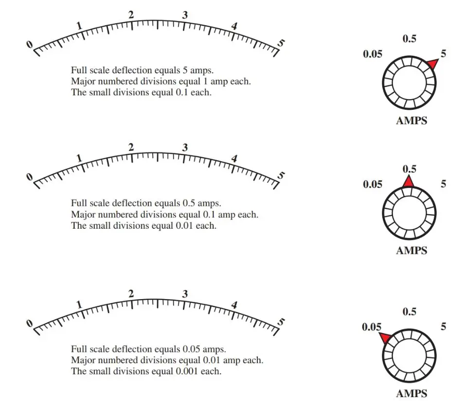
Figure 5. Typical linear meter scale.
The scale illustrated in Figure 5 is marked from 0 to 5 with ten smaller marks between each major numbered mark.
To determine the value of each mark between the major divisions (the scale factor), divide the value of the first major division by the number of spaces in that division.
The dial to the right of each scale in Figure 5 is the range selector. The range selector must be correlated to the scale to determine full-scale deflection. The formula for scale factor is as follows.
\[\text{Scale Factor=}\frac{\text{Value of major division}}{\text{number of spaces}}\]
Study Figure 5. Note that the value of each division changes as the range selector changes. On the scales, the first major division is marked with a one (1).
In the top example, the range selector is set on 5 amps. This means that the full-scale deflection is 5 amps. On this scale, the one (1) represents 1 amp. There are ten spaces between the one and the zero. By dividing one by ten, we can conclude that each space is equal to one-tenth (0.1) of the first major mark or 0.1 amp.
The second example has a full-scale deflection equal to 0.5 amperes. Therefore, the major scale markings are equal to 0.1 ampere each. Since there are ten spaces between each major division, each small mark is equal to 0.01 amperes each (10 milliamps).
In the third example, the range selector switch is set at 0.05 amps. This makes the full-scale deflection equal to 0.05 amperes. Each major numbered division is equal to 0.01 ampere. Since there are ten equal spaces between each major division on the scale, each small mark is equal to 0.001 amperes or 1 milliamp.
Analog Meter Movement Key Takeaways
The D’Arsonval and iron vane meter movements play a crucial role in the accurate measurement of current and voltage in various electrical applications. These meter movements are vital in fields such as electrical engineering and maintenance, where precise readings are necessary for troubleshooting, calibration, and ensuring the safety and efficiency of electrical systems. Their principles of operation and reliable scaling make them indispensable tools for measuring electrical parameters in both low and high-power circuits.
Top Selling Electrical Testing Tools
[amazon_auto_links id=”22869″]