The article explains the fundamental components of an electrical circuit, including the source, load, and conductors, and covers key concepts such as voltage, current, resistance, and the differences between AC and DC currents. Additionally, it discusses electron flow theory, series and parallel connections, and provides insights into how materials affect electrical conductivity.
Electrical Circuit Components
A basic electrical circuit consists of three main components, a source of voltage, a load, and conductors. In Figure 1, a basic circuit is illustrated. This circuit consists of a battery as the source of electrical energy, a lamp as the electrical load, and two wires as the conductors connecting the battery to the lamp.
Battery
In the source of this circuit, the battery, a chemical reaction takes place that results in ionization. This ionization produces an excess of electrons (negative charge) and a depletion of electrons (positive charge).
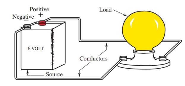
Figure 1. A basic electrical circuit (Diagram) consists of three main components: the source, the load, and the conductors.
The battery has two terminals. These terminals are connection points for the two conductors. One terminal is marked with a plus sign (+) and the other a negative sign (–). These two markings are referred to as polarity markings.
Not all electrical devices have polarity markings. However, when polarity is a critical issue, it will be marked on the device. The proper polarity must be followed to avoid damage to equipment and/or personnel.
Load
A load is created when the electrical energy produced in a circuit is converted to some other form of energy such as heat, light, or magnetism. The load in the simple electrical circuit of Figure 1 is a lamp that produces light.
The source and the load should match according to the voltage rating. If the lamp is rated at 6 volts, then the battery should also be rated at 6 volts.
If the battery is rated at a lower voltage rating, the lamp will appear dim or will not light. If the battery is rated at a much higher voltage, the lamp will be damaged by the excess electrical energy.
Conductor
The conductors we are using are two copper wires covered with a plastic insulation coating. The copper wire provides a path through which the electrical energy can flow, while the plastic coating restricts the electrical energy to the copper wire. This makes the conductor pathway safe for personnel.
This completes the description of the basic components of an electrical circuit in which electrical energy is channeled by way of electrical conductors, through a device, where it is then converted to some useful form.
Voltage
Ionization can be caused by forces such as heat, light, magnetism, chemical action, or mechanical pressure. This results in the creation of an electrical voltage.
What is Voltage? Voltage is the force behind electron flow. In the simple electrical circuit just described, the battery was the source of electrical energy. This battery has a rating of 6 volts.
The volt (V) is the electrical unit used to express the amount of electrical pressure present, or the amount of electrical force produced by the chemical action inside the battery.
The term voltage is used to express the amount of electrical force in much the same way we use horsepower to express the amount of mechanical force for an automobile.
Electrical pressure or voltage can also be expressed as potential, potential difference, or as electromotive force (emf). For our purposes, these terms mean the same thing. Voltage is usually represented by the capital letter E or V.
Current
Electrical current is the flow of electrons. The amount of electrons flowing past any given point in one second is rated in the electrical unit ampere (A).
The ampere is expressed using the letter I. Remember that a coulomb is a number of electrons.
The ampere describes the rate of flow of the electrons past any given point in a circuit. One ampere is equal to one coulomb of charge flowing past a point in one second.
Compare a balloon filled with air to an electrical battery. In Figure 2, the amount of air molecules in the balloon represents the number of electrons or coulombs. The amount of air pressure inside the balloon is expressed as pounds per square inch (PSI) of air pressure.
In the battery, the amount of electrical pressure inside the battery is expressed as the voltage rating of the battery.
The rate of air flow out of the balloon is similar to electron flow, or current, from the battery. The current from the battery in the electrical circuit is the volume of electron flow past a given point and is rated in amperes or amps.
Just as the air will continue to escape from the balloon until the balloon is empty, the electron flow can continue as long as there is voltage or electrical pressure present in the battery.
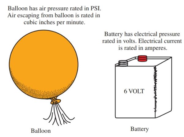
Figure 2. A balloon is similar to an electrical source. Air escaping from the balloon is similar to electrons flowing from a source.
Resistance
All electrical circuits have resistance. Resistance is the opposition to the flow of electrons. Resistance is measured in ohms, and the electrical symbol for ohm is Ω (the Greek letter omega).
The resistance values of elements and compounds differ according to the atomic structure of the material.
A good conductor of electricity is anything that permits the free flow of electrons. A poor conductor of electricity is a material that will not permit the free flow of electrons. Extremely poor conductors are referred to as insulators.
A semiconductor is a material that limits the flow of free electrons. A semiconductor is considered neither a good conductor nor poor conductor of electricity. Semiconductor materials are at the very heart of the modern electronic application. Some examples of conductors and insulators are listed in Figure 3.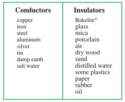
Figure 3. Common conductors and insulators Examples
Note that the earth can be a good conductor of electricity. There are many factors that determine whether or not the earth will be a good conductor.
The earth’s conductivity is primarily dependent upon its organic composition and on the minerals found in the soil at any given place.
The amount of moisture in the soil also determines the amount of resistance in the soil. Moisture can affect the electrical conducting ability of many materials. It can even cause an insulator to become a good conductor.
Take wood as an example to illustrate this point. When wood is dry, it is classified as an insulator, but when wood becomes wet or moist, it behaves more like a semiconductor.
It is the outer ring of an atom that determines whether an element is a good or poor conductor. If the outer ring has only one electron, that electron can be freed from its orbit rather easily by an outside force.
If there are many electrons in the outer orbit, the electrons are held tighter in orbit. They are harder to free from the atom. Elements that do not readily give up an electron are insulators.
Figure 4 is an illustration of the copper atom. Notice how this atom has only one electron in its outer orbit. This electron can be easily freed by an outside force. Copper is an excellent conductor of electricity.
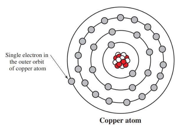
Figure 4. The element copper is an excellent conductor. It has only one electron in its outer orbit. This electron can be easily released from its orbit by an outside force.
- You May Also Read: Difference between Conductor Semiconductor and Insulator
Electric Current, AC and DC
There are two types of electrical current, dc (direct current) and ac (alternating current). The difference between these currents is how they flow through an electrical circuit.
Direct current flows in only one direction through an electrical circuit. An example of direct current is a standard battery. The battery has a set polarity (positive and negative terminals) and will produce an electric current in only one direction.
On the other hand, alternating current, as its name implies, flows in both directions. First, it flows in one direction, and then it reverses its flow to the opposite direction. See Figure 5.
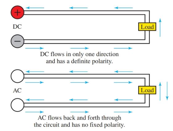
Figure 5. Direct current flows in one direction while alternating current repeatedly alternates direction.
There are no positive or negative polarity markings in alternating current because the polarity changes so rapidly in the typical AC electrical circuit.
The terms cycle and hertz are used to describe how fast the current is alternating or changing direction in the circuit.
A 60 cycle AC circuit (operating at 60 hertz) changes direction 120 times per second. This is the standard for AC in the USA.
Conventional Current Flow vs. Electron Flow Theory
Approximately 200 years ago, scientists theorized that electricity had both positive and negative polarities. At that time they arbitrarily decided that electrical current flowed from positive to negative. While it was never actually proven as fact, this theory was accepted for quite some time. This theory is known as the conventional current flow theory.
As our knowledge of science progressed, and with the discovery of the atom and semiconductor electronics, it became apparent that the conventional current flow theory was incorrect. It is widely accepted that it is the electrons that actually move, flowing from negative to positive, not from positive to negative. This newer theory is known as electron flow theory.
- You May Also Read: Difference between AC and DC Current
The emergence of this new theory caused a controversy that is still in existence today. For over 150 years all circuit designs had been based upon the old, conventional current flow theory.
Many circuits and devices still used today are based on the conventional theory. Regardless of which theory is used to explain the phenomena of electronics, the most important point is that the correct polarity must be maintained when building circuits with devices that require a definite polarity. See Figure 6.
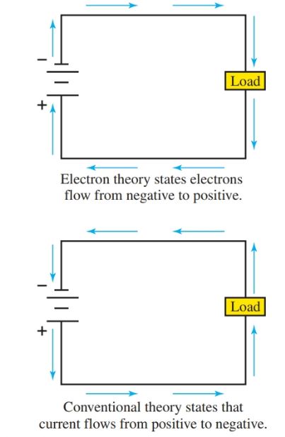
Figure 6. Electron flow theory and conventional current flow theory.
Types of Electrical Circuit
There are two ways a component can be connected in an electrical circuit, either series or parallel. Figure 7 and Figure 8 illustrate the two types of circuit connections.
The circuit in Figure 7 has three lamps connected to a battery. In this circuit, there is only one path over which the electrons can flow.
When electrons only have one circuit path to follow, that circuit is called a series circuit. The lamps are said to be wired in series with respect to each other.
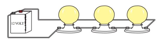
Figure 7. Three lamps connected in series configuration
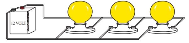
Figure 8. Three lamps connected in parallel configuration
In Figure 8, there are three lamps connected in parallel. In this circuit, there are three different paths for the electrons to follow from the battery terminal to the battery terminal.
Electrical Circuit Key Takeaways
In conclusion, understanding the fundamental components of electrical circuits—such as voltage, current, resistance, and circuit configurations—is essential for practical applications in various fields. From powering household appliances and industrial machinery to enabling complex electronic systems in computing and telecommunications, these principles form the foundation of modern technology. The distinction between AC and DC currents, along with knowledge of series and parallel connections, is crucial for designing efficient and safe electrical systems.