This article reviews methods for measuring force and torque using calibrated transducers, including strain-gauge-based load cells, force-sensing resistors, and reaction and rotary torque sensors. It explains their operating principles, signal conditioning requirements, and multi-axis sensing configurations used in modern engineering applications.
There are two methods to measure forces and torques. One is the direct comparison method, which is based on the use of some form of beam balance with known weights. The other is the indirect comparison method, which is based on the use of calibrated transducers. This article focuses on the second method since the output of the transducers can be easily interfaced with a PC or a microcontroller.
Force Sensors
Transducer-type force sensors or load cells can be hydraulic, pneumatic, or strain-gauge-based. Hydraulic load cells measure the weight by sensing the pressure change in the fluid system, while pneumatic load cells measure changes in air pressure. Strain-gauge types are one of the most common types. They are based on the use of an elastic element combined with one or more strain gauges. The resistances of the gauges are processed by a Wheatstone bridge circuit. Strain gauge load cells are available in different configurations:
- Compression type
- Tension/compression type
- S-beam load cells
- Universal mounts
- Rectangular beam cells
A schematic of these configurations is shown in Figure 1.
- The compression-type cell is designed to handle compressive loads. It has a low profile and a small size, and it can be made to handle high loads that must be centered.
- The tension/compression type can handle both compressive and tensile center loads.
- The S-beam load cell can also handle both compressive and tensile loads, but it is better suited for harsh environments and offers good resistance to side loads.
- The universal mount is similar to the compression type, but it can handle off-center loads.
- The rectangular beam is a low-cost sensor that can handle compressive eccentric loading. This design is also known as the single-point load cell.
Load cells typically use more than one strain gauge to increase the sensitivity of the sensor. In many cases, four strain gauges are used as seen in Figure 2, and they are laid out so that the change in resistance of the strain gauges under the applied loading adds to improve the output of the Wheatstone bridge. Strain gauges with a 350 Ω resistance are commonly used in load cells.
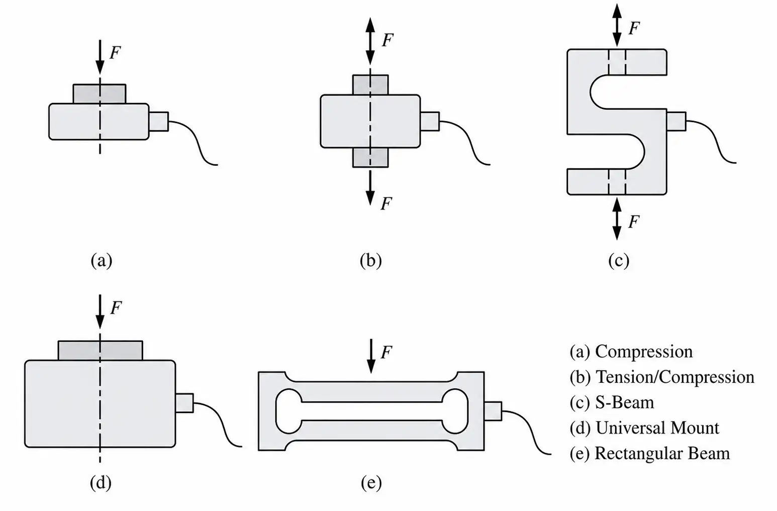
Figure 1. Different configurations of load cells
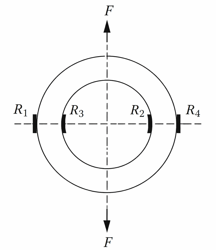
Figure 2. Four strain gauges used in a load sensor
Manufacturers of load cells list the output of the load cells in mV/V (such as 2 mV/V). Due to the use of Wheatstone bridge circuitry, the output is directly related to the excitation input. For example, if the supply voltage is 10 V, then the full-scale output of the load cell is 20 mV for a load cell with a 2 mV/V output rating. To make this output more usable, especially with display devices or microcontrollers, an external amplifier can be employed to amplify the signal.
Load cells are calibrated to ensure their outputs correspond to specific units of measurement, such as pounds (lbs.) or Newtons (N). Like all sensors, load cells have inherent inaccuracies. They are particularly sensitive to thermal errors, often resulting from the thermal expansion or contraction of the materials used in the load cell’s design.
Force-Sensing Resistor
A force-sensing resistor (FSR) is a sensor that measures applied force through changes in its electrical resistance, and Figure 3 shows a photo of an FSR with a round active area. The sensor is constructed using a conductive polymer layer situated between two substrate layers, with the outer layers often having conductive materials serving as electrodes.
When force is applied to the FSR, the conductive particles within the polymer come closer together, which causes a decrease in its resistance. However, it is important to note that this relationship is nonlinear; the resistance does not decrease proportionally with increased force.
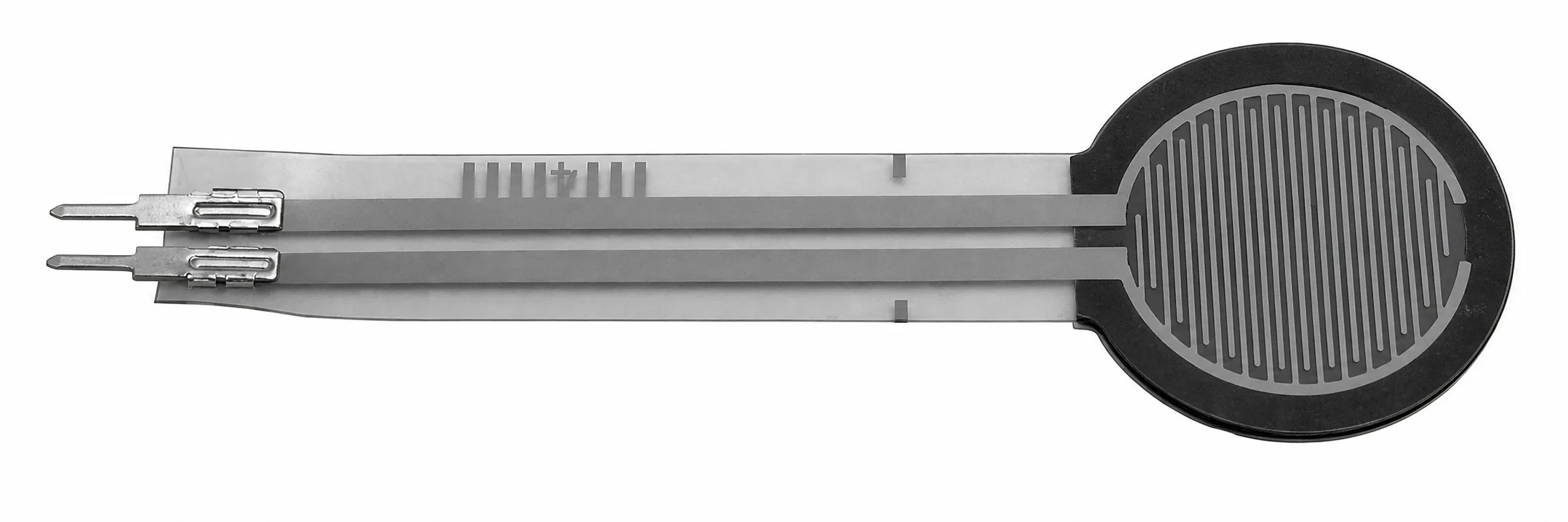
Figure 3. Force-sensing resistor
One of the primary applications of FSRs is in scenarios where the relative change or simple detection of force is more vital than the precise force measurement, such as in touch controls.
Despite its low cost, thin profile, flexibility, and simplicity—highlighted by its two-lead design—the FSR comes with inherent disadvantages. It is known for its low accuracy, and its high resistance, especially under slight pressures, can lead to significant loading effects in circuits with lower input impedances. To address this, when integrating an FSR into circuits, it is often placed in a voltage divider configuration with a fixed resistor. The chosen value of this fixed resistor plays a crucial role in optimizing the sensor’s sensitivity and range for specific applications.
Moreover, to mitigate loading effects, a voltage follower (or buffer) circuit can be employed. Example 1 discusses the use of an FSR and its wiring to minimize loading effects. It is also worth noting that besides the low accuracy and potential loading effects, FSRs can exhibit hysteresis and might face durability concerns in high-cycle applications.
Example 1 Wiring of an FSR Sensor
Illustrate how a typical FSR sensor can be wired to minimize loading effects.
Solution
A typical FSR wiring to minimize loading effects is depicted in Figure 4. An FSR is typically connected with one end to a voltage supply, Vin , and the other end to a pull-down resistor, R, grounded to create a voltage-dividing circuit.
The voltage output taken from the point between the fixed pull-down resistor and the FSR serves as the FSR’s output.
The value of R usually lies between 10 and 100 kV. It is adjusted to fine-tune the sensitivity and range of the force sensor readings. Increasing the reference resistance R makes the sensor more sensitive (i.e., small changes in force result in larger voltage changes), but the downside is that the sensor can become saturated or maxed out at lower forces, hence reducing the overall force range over which the sensor can distinguish different force levels.
The output from the voltage dividing circuit is subsequently passed to a voltage follower or buffer. This buffer offers a high input impedance to the FSR and a low output impedance to the following circuitry, ensuring precise voltage reading values.
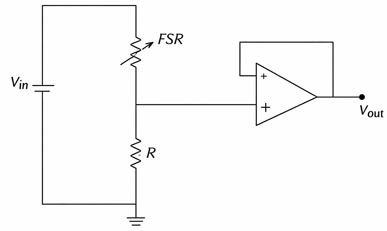
Figure 4. FSR wiring to minimize loading effects
Torque Sensors
Measurement of torque is done using two different configurations of sensors. These are the reaction torque sensors and the rotating torque sensors. Both configurations are based on the use of strain gauges that are mounted on elastic members. The elastic element in both configurations of torque sensors could be a solid or hollow circular shaft, a solid or hollow cruciform, or a solid square shaft (see Figure 5).
Hollow cruciform is typically used for low-torque measurement applications, while solid circular and square shafts are used for high-torque applications.
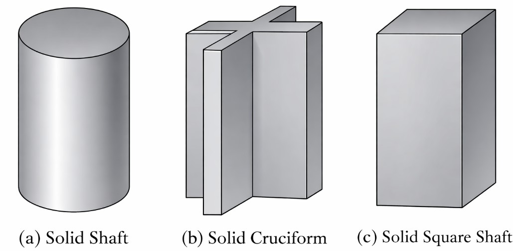
Figure 5. Schematic of different elastic elements used in torque sensors
The reaction torque sensor is used to measure torque in non-rotating applications. In this configuration, the sensor is stationary, and the shaft of the part of which the torque needs to be measured is connected through a coupling to the sensor. Reaction torque sensors are used, for example, to measure the motor torque output at zero speed or the starting torque. Other applications include bearing friction measurement and automotive brake torque sensing.
The rotary torque sensor on the other hand is used to measure torque between rotating devices. The sensor is typically mounted in-line between the torque source and the load. Typical applications for rotary torque sensors include engine dynamometer testing, fan and blower testing, and clutch testing.
Figure 6 illustrates the use of these two sensors. Similar to load cells, torque sensors give an output voltage that is proportional to the applied torque.
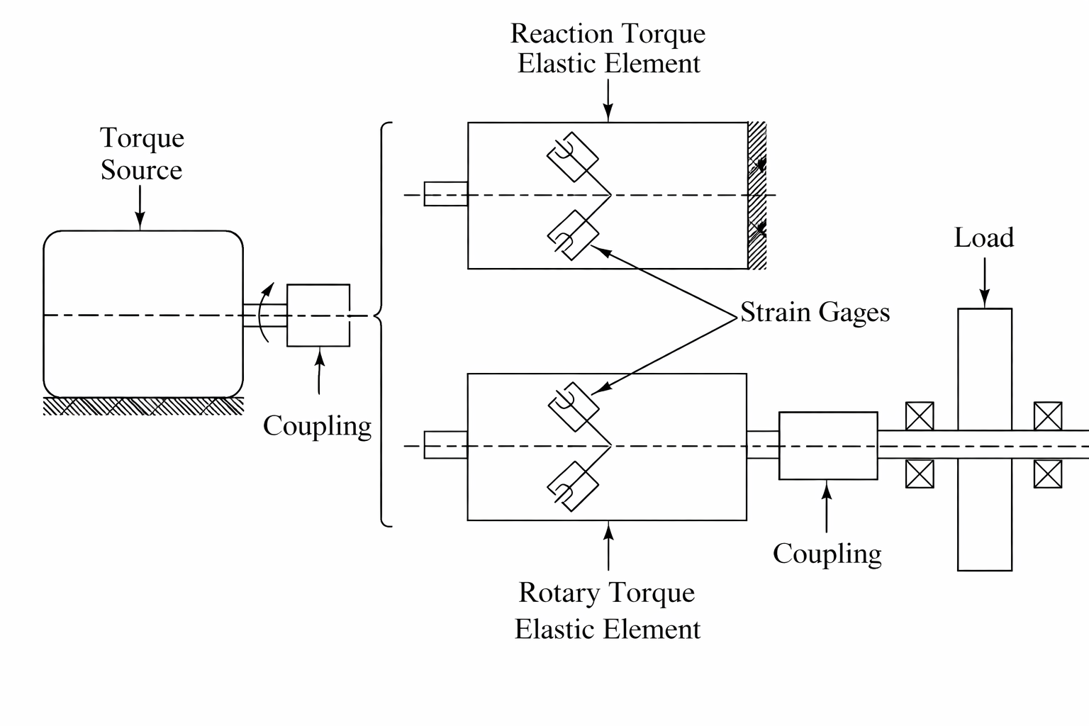
Figure 6. Illustration of reaction and rotary torque sensors
Since the sensing element is rotating in a rotary torque sensor, inertia effects are important. This is especially important during the power-up and power-down phases of the rotating member when the rotational speed is not constant. Thus, torque sensors with low inertia are desirable.
Also, means must be provided to transmit the sensor signals from the rotating strain gauge transducer to the stationary electronics. Common methods for transmitting the signals include the use of slip rings and rotary transformers.
- Slip rings are similar to a commutator in a brush DC motor and are suitable for low–rotation speed applications. At speeds above 5000 rpm, the noise induced by brush friction makes them not very suitable.
- A rotary transformer is a non-contact device and is like a regular transformer, but the secondary coil is rotating relative to the primary coil. Two rotary transformers are used: one for transmitting the supply voltage to the Wheatstone bridge circuit and the other for transmitting the output from the bridge circuit (see Figure 7).
Some rotary torque sensors also output the rotation angle of the sensor, which is obtained from an encoder that is built into the sensor. Reaction torque sensors have a higher torque-measurement capability than rotary torque sensors, and some units are made to measure torque values up to a few million-pound inches.
End connections to both configurations include the use of a keyed shaft, a flange, or a spline. Figure 8 shows commercial reaction and rotary torque sensors with keyed shaft coupling.
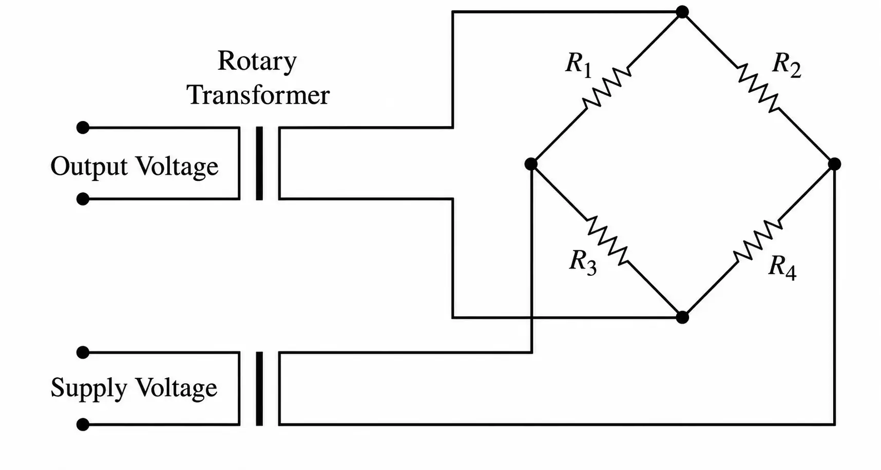
Figure 7. Wheatstone bridge with rotary transformers
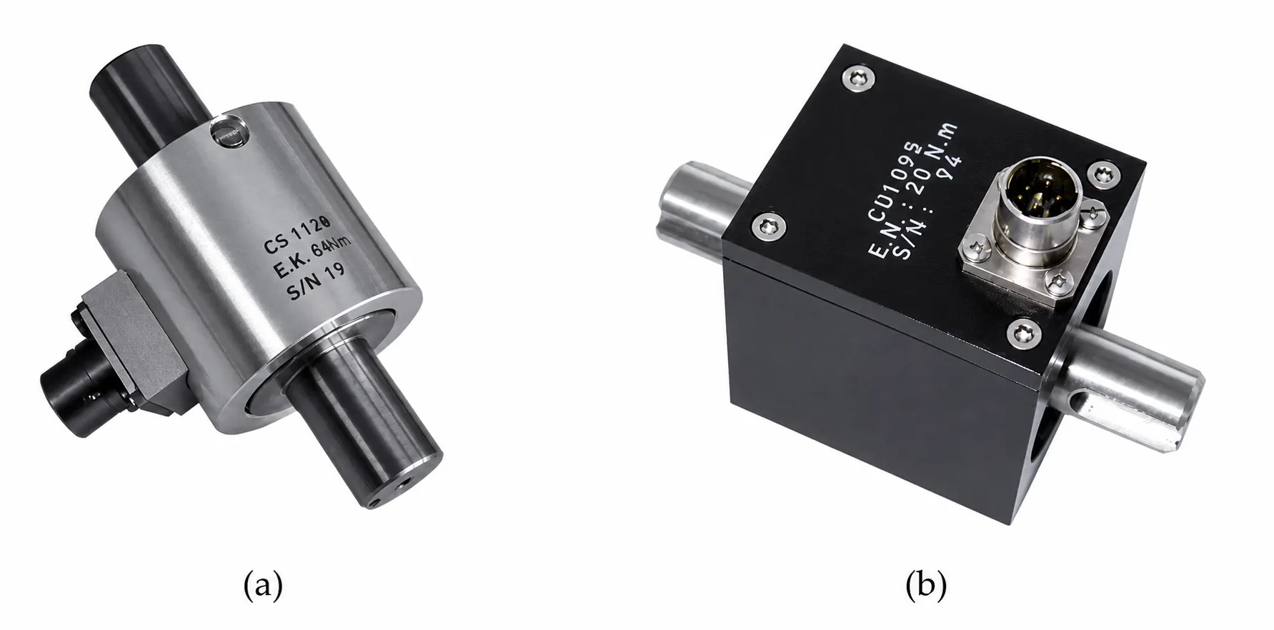
Figure 8. Commercial (a) reaction (Model CS1120) and (b) rotary torque (Model CD1095) sensors with keyed shaft coupling
Multi-Axis Force/Torque Sensors
Many applications require the measurement of force and/or torque on more than one axis. These include robotic applications in which the robotic arm interacts with the environment such as assembly where force and torque sensing is used to detect misalignments for quality control and for ensuring proper assembly; material testing and research where force and torque measurements in multiple axes are used for structural analysis, material characterization, and studying mechanical properties under different loading conditions; and rehabilitation and prosthetic devices where force and torque sensors capture forces and torques applied during movements, enabling precise adjustments and customization of prosthetics for individual users.
A widely used multi-axes force/torque sensor is the six-axes force and torque sensor, also known as a six-axis load cell, which measures forces and torques along three orthogonal axes (X, Y, Z) and their corresponding moments or torques.
The sensor typically consists of a rigid mechanical structure that can withstand and distribute applied forces and torques. Inside the sensor, strain gauges are bonded to the sensor’s structure and strategically placed in specific locations to measure the strain caused by applied forces and torques.
A picture of the inner details of a commercially available 6-axis sensor is shown in Figure 9. An inner hub to which the external forces and forces are applied is connected to the frame or outer wheel of the sensor through three beams or spokes that are spaced 120 degrees apart. Each beam has four strain gauges, with one gauge placed at each of the four surfaces of the beam. These gauges function in pairs, with each pair forming a half-bridge of the Wheatstone bridge used to process the signals from these gauges.
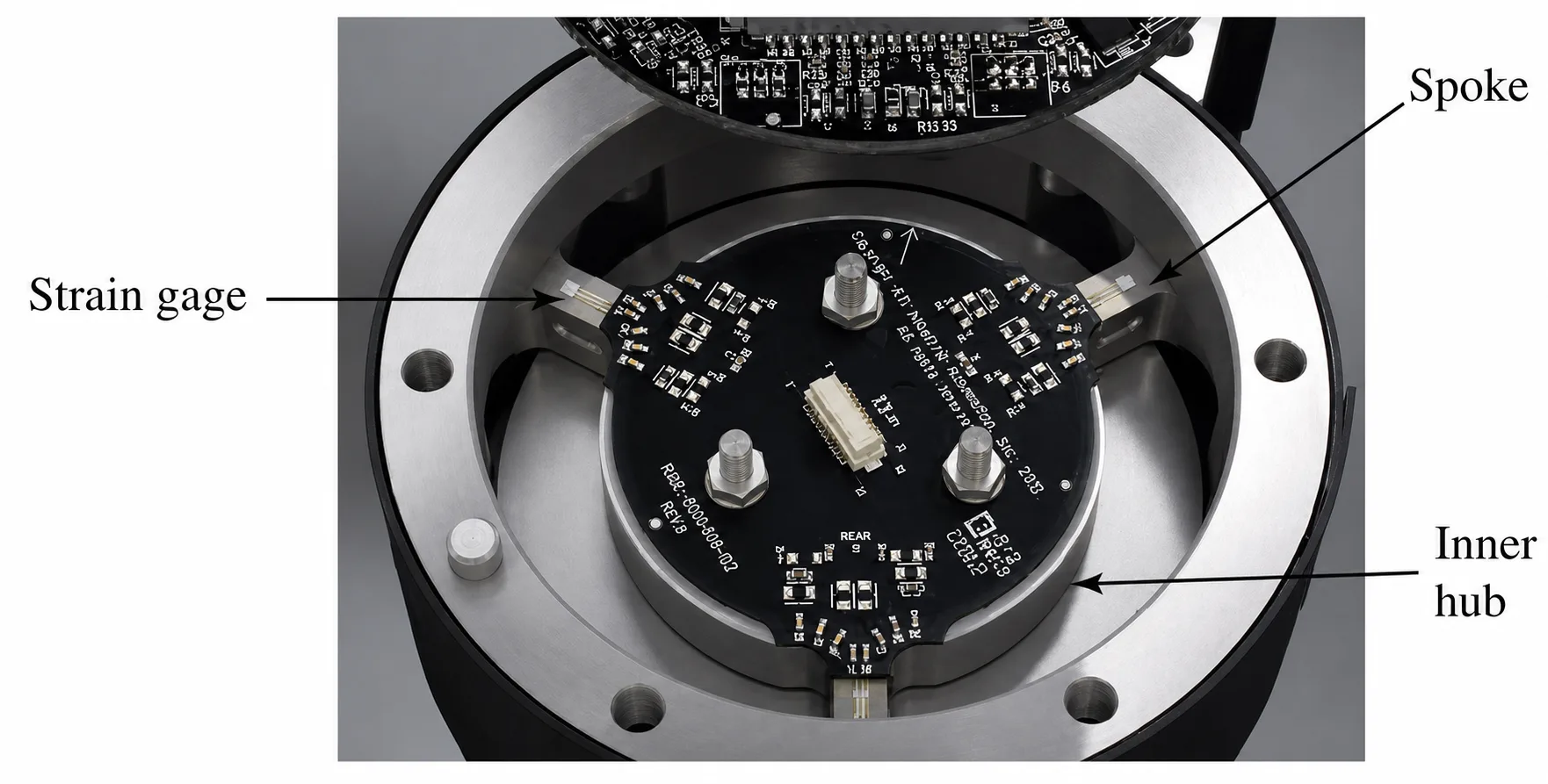
Figure 9. Inner details of a commercial 6-axis force torque sensor
Key Takeaways
Force and torque sensors play a critical role in mechanical testing, industrial automation, robotics, automotive systems, and research laboratories where accurate load and rotational measurements are essential for performance evaluation and control.
Strain-gauge-based load cells and torque sensors provide high precision and reliability for structural and dynamic measurements, while simpler devices such as force-sensing resistors serve cost-sensitive or relative-force applications.
Multi-axis force/torque sensors further expand capability by enabling simultaneous measurement of forces and moments in complex interaction environments. A clear understanding of sensor selection, calibration, signal conditioning, and mechanical integration ensures dependable measurements and supports safe, efficient, and optimized system design across a wide range of engineering applications.